Optimal print quality requires that the printheads be properly aligned. Printhead alignment is done during the initial setup process and may be done as a maintenance task at other times if needed.
Preliminary Checks
The following steps should be taken before changing the printhead alignment. Modifying the alignment without first completing these checks may result in misaligning the printheads while unintentionally compensating for a mechanical issue.
- Ensure that the printer is level, adjusting the height of the table’s four feet/casters as needed.
- Ensure that the distance between the top of the platen and the bottom of the printhead mounting bracket is the same at each of the platen’s four height adjustment screws.
- Clean the encoder strip.
- Clean and lubricate the carriage rails.
Alignment Process Overview
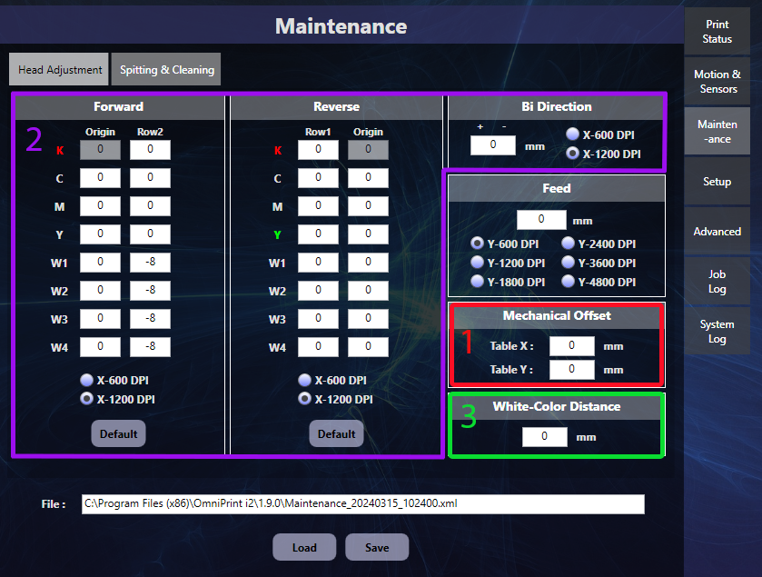
The Head Adjustment tab of the i2 UI program’s Maintenance screen is where adjustments are made, in response to visual feedback from test pattern prints.
- The Mechanical Offset is adjusted first to position the starting x,y position (0,0 by default) at the flat front-right corner of the platen — inside the beveled edge.
- Forward, Reverse, and Bi-directional (horizontal) alignment must be done at the 1200 DPI setting.
- Vertical alignment between the two heads is done using the White-Color Distance control.
Let’s get started!
Mechanical Offset
The Mechanical Offset‘s ‘Table X’ and ‘Table Y’ settings calibrate the top-left corner of print jobs, which may also be thought of as the near right corner of the platen when viewing from the front of the printer.
i2 platens have an approximately 1/8″ bevel around their outside edge. This should not be considered part of the platen’s printable area. We want to confirm that a nozzle check print has its top-left corner (bottom-right from the front of the printer perspective) at the edge of the flat area of the platen. There should be virtually no space between the platen’s flat edges and the ink, and there should be no ink on the beveled part of the platen.
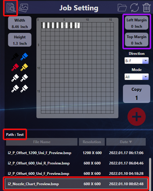
- Select the i2_Nozzle_Chart_Preview.bmp file from the Test path in the i2 UI software’s Job Setting section.
- Set both the Top & Left Margins of the Job Setting section to ‘0’.
- Send the job to the print queue and print it.
If the top-left corner of the nozzle check pattern print isn’t positioned at the corner of the platen (the flat part of the platen, not on the beveled edge) then we’ll need to change the X value (for horizontal adjustments) and/or the Y value (for vertical adjustments).
Increasing the values shifts the print toward the center of the platen. Decreasing the values shifts the print towards the edges of the platen.
Horizontal Alignment
There are three horizontal alignments: Forward, Reverse, and Bi-Directional. These names describe carriage movement when printing occurs — when the carriage is moving in the forward direction only, in the reverse direction only, or in both directions. Most printing is done bi-directionally for the speed benefit, but alignments for all three types of printing must be performed.
The process for checking and adjusting the Forward & Reverse alignments are identical so we’ll provide step-by-step details for the Forward alignment, and only list the differences for the Reverse alignment.
Forward horizontal alignment
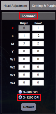
- Select the ‘X-1200 DPI’ setting at the bottom of the Forward section on the Head Adjustment tab of the i2 UI software’s Maintenance screen.
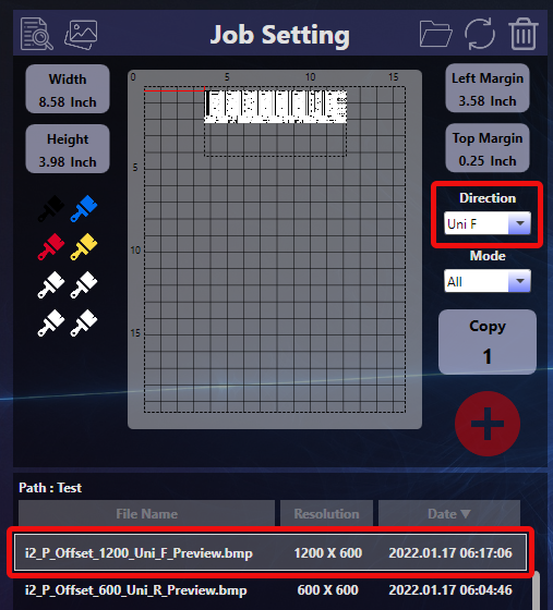
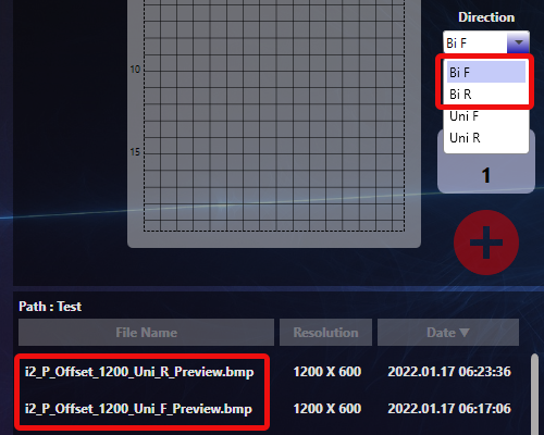
- Set Direction to ‘Uni F’ and select the i2_P_Offset_1200_Uni_F_Preview.bmp test file in the Job Setting section of the i2 UI software. The image can be positioned as desired to use available space on a DTF sheet or other transparent plastic sheet.
- Print the test image.
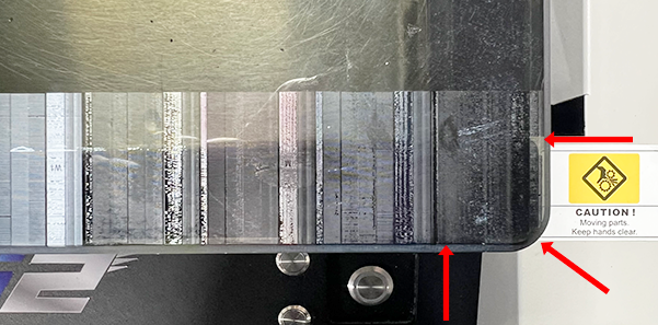
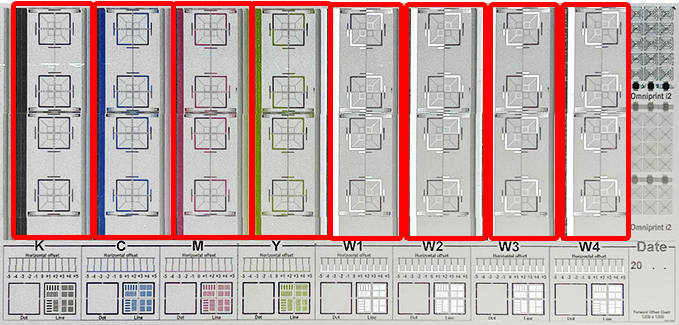
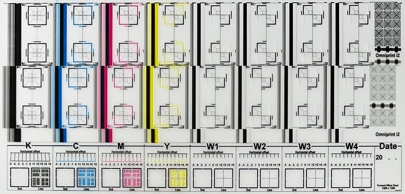
- Analyze the test print to determine if adjustments are needed, focusing on the highlighted area in the image below.
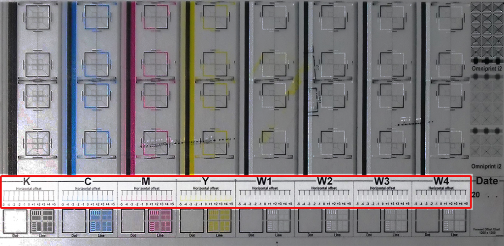
- First analyze the four white channels, W1, W2, W3, and W4.
- Each section (W1, W2, W3, and W4) has a series of numbers going from -5 to +5. Above each number are black & white vertical line segments. For each of these ‘W’ groups, identify which black & white pair form a single straight vertical line, or which is closest to a straight vertical line if none are perfectly aligned, and note the corresponding number of each.
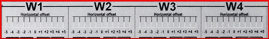
In the pictured example, we would note the following:
W1: +3
W2: 0
W3: +1
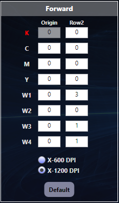
W4: +1 - The next step is to sum (or add) the noted numbers to the values currently appearing in Row2 of the Forward Head Adjustment section. The image at the top of this section shows that the Row2 values in the Forward section for W1, W2, W3, and W4 are all ‘0’, so we have the easiest possible math of simply adding the noted numbers to 0.
- After updating the values, click the Save button at the bottom of the Maintenance screen.
- Loop through steps 3 through 7 until the black & white line segments for W1, W2, W3, and W4 each form straight vertical lines in the 0 (zero) position.
- Once the whites are all aligned, find the number associated with the best-aligned vertical line pairs for Cyan, Magenta, and Yellow and sum them with numbers currently in the C, M, and Y rows of Row2.
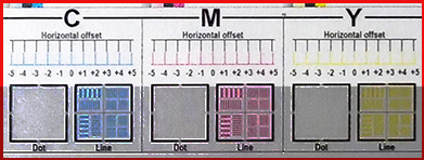
- The CMY channels in the above example already have the vertical lines perfectly aligned in the 0 (zero) position.
Reverse horizontal alignment
The process for the Reverse alignment is identical to the Forward alignment with the following exceptions.
- Select the ‘X-1200 DPI’ setting at the bottom of the Reverse section on the Head Adjustment tab.
- Select i2_P_Offset_1200_Uni_R_Preview.bmp in Job Setting.
- Set Direction to ‘Uni R’.
- When updating values based on analysis of the test print, sum with the current numbers in Row1 in the Reverse section of the Head Adjustment tab.
Bi-Directional horizontal alignment
Once the Forward and Reverse alignments are completed, we want to make sure the horizontal alignment is also good when printing in the Bi-directional mode.
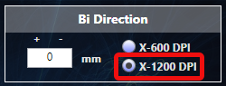
Start by clicking the X-1200 DPI option in the Bi Direction box.
Bi-directional alignment teseting can be done using either of the 1200 Uni offset test patterns: i2_P_Offset_1200_Uni_R_Preview.bmp or i2_P_Offset_1200_Uni_F_Preview.bmp.
Likewise, the Direction option in Job Setting can be set to either Bi F or Bi R.
After printing a test pattern, analyze the eight columns of stacked squares (one for each color channel), where each square is divided into four smaller squares.
In the above example, we can see that the bi-directional alignment is good because the upper pair of boxes in each column is aligned with the lower pair of boxes.
In the below example, the bi-directional alignment must be adjusted to make the upper and lower pairs of boxes line up with each other.
The position of the lower pair of boxes in each column is offset to the left of the upper pair of boxes (as well as the rest of the test pattern) by approximately 3mm. So to correct the alignment we will need to adjust the Bi Direction value by 3mm.

In this example, the Bi Direction value was set to zero (“0”) but you may find another number on your installation. To adjust the alignment we’ll want to change the value by either adding (+3) or subtracting (-3) to the current of zero.
Here’s how to know if you need to enter ‘3’ or ‘-3’ (the ‘+’ sign is not used).
If the above example was printed using the Bi F direction setting then we would enter ‘-3’, or if printed using the Bi R direction setting we would enter ‘3’.
Don’t worry too much about remembering which offset direction calls for entering a larger or smaller number. You can always change directions (upward or downward) if your entry made the offset worse. You can also use decimal fractions (2.7, for example) to fine-tune the alignment.
Remember to Save after each change before printing the next test patter.
White-Color Distance (Vertical Alignment)
Vertical alignment of the two printheads is done using the White-Color Distance setting. As the software’s label describes, performing a vertical alignment is essentially calibrating the vertical position of the two printed ink layers as laid down by the separate white and color (CYMK) printheads.
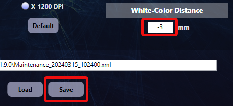
Rather than using numbered line segments in a test pattern, as in the horizontal dimension, we simply evaluate any test pattern or design print. The adjustment is made by entering the number (in millimeters) by which the layers are out of alignment.
For example, let’s say the white layer is printing 3 mm above the color layer (as prints are oriented on the platen with the top of the design toward the front of the printer). To adjust the alignment we would enter “-3” in the White-Color Distance text box, then click the Save button.
After making an adjustment we always run another test print to see if we nailed it or if we need to make another adjustment.
You can have very high confidence that you will get excellent accuracy and detail when printing even the most challenging designs with all of the alignment options optimized!
Not finding what you need?
You can contact our technical support team by sending an email to support@omniprintonline.com with your company name, contact name, phone number, printer serial number, and a quick description of how we can help you.
This will automatically open a support case for you in our ticketing system and a technical support rep will follow up with you shortly.