- 1. Preparing the Space
- 2. Power requirements
- 3. Space requirements
- 4. Assembly & Setup
- 5. Demonstration video
- 6. Positioning & Leveling the Printer & Oven
- 7. Removing the Carriage Lock Bracket
- 8. Loading the Film
- 9. Attaching the Takeup Roll Assembly
- 10. Attaching the Fan Assembly
- 11. The Powder Keeper
Ease of setup is one of the benefits of the Omni DTF Mini system. In this article we’ll walk step-by-step through the process of getting your equipment positioned, fully assembled, and loaded with film so it’s ready for your training session.
For demonstrations of the steps, see the embedded videos covering the equipment assembly & setup details and use of the Powder Keeper in their respective sections below. Note that there is also a link to our Unboxing the Omni DTF Mini article and video at the bottom of this page.
Preparing the Space
Power requirements
The Omni DTF Mini’s oven must be powered from its own dedicated 20 amp circuit, while the printer’s more modest power requirements allow it to be used on circuits shared with other devices, including the air purifier. All of the equipment should be powered through surge protectors, rather than plugging directly into an outlet. As with any electronic equipment, damage caused by electrical storms or any irregular power problems is not covered by the warranty, since such damage is not due to a defect in parts or workmanship.
| Equipment | AC Voltage | Peak Current |
|---|---|---|
| Omni DTF Mini printer | 110-120 VAC | 2.5A |
| Omni DTF Mini oven | 110-120 VAC | 19.5A |
| Air purifier | 110-120 VAC | 1.65A |
Space requirements
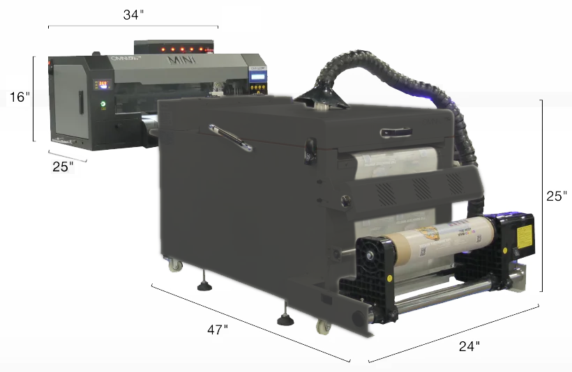
It’s necessary to be able to move around the printer and oven to ease doing things like loading new rolls of film, circulating the white ink, cleaning the undercarriage, refilling the powder hopper, and removing completed prints.
Assembly & Setup
Demonstration video
Positioning & Leveling the Printer & Oven
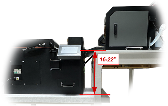
When selecting a desk or bench for the printer and oven, keep in mind that the top surface of the oven’s table or bench should be 16″ to 22″ below the top surface of the printer’s table. This provides a sufficient drop to support the film advancing consistently. Greater distances may result in poor transfers and durability issues due the ink drying too much before powder is applied.
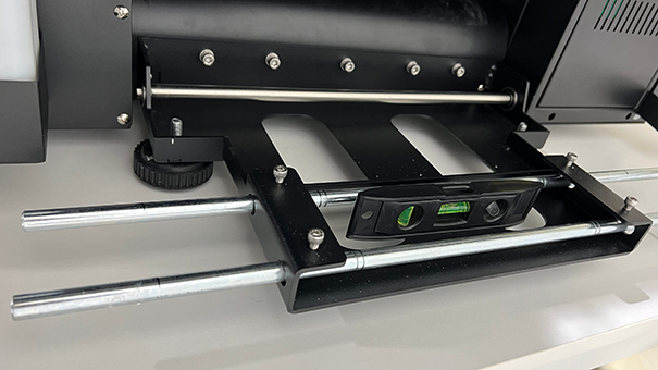
The printer’s four feet are mounted onto bolts which can be rotated to lengthen or shorten their length.
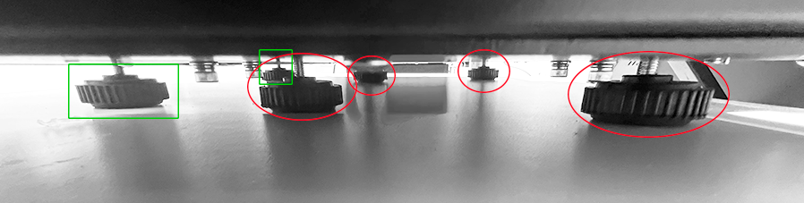
These should be adjusted so that the printer is level, while the feet supporting the film roll bracket (also shown below) should be at their minimum length.
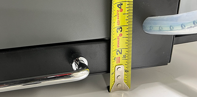
While leveling, keep in mind that the printer’s feet should elevate the bottom of the printer at least 1″ above the surface of the table or bench that it rests on.
The oven assembly’s feet also have adjustable length bolts for leveling the equipment.
Removing the Carriage Lock Bracket
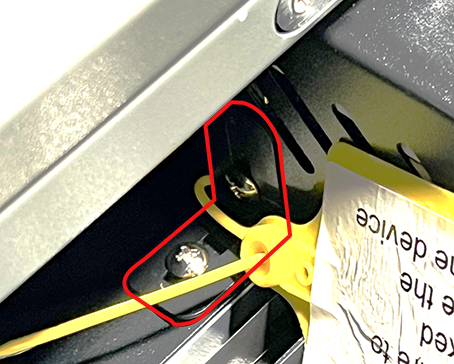
The printhead carriage is locked in place to prevent potential damage due to motion during shipment. Be sure to remove the locking bracket prior to connecting to power and turning on the printer.
The bracket attaching the left side of the printhead carriage to the carriage frame is removed by taking out the two screws that hold it in place.
Loading the Film
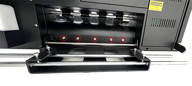
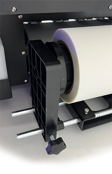
First, attach the factory-assembled film roll support bracket to the back of the printer. Remove the five Allen head bolts, line up the bracket with the holes those bolts were removed from, then reinstall the bolts to attach the bracket.
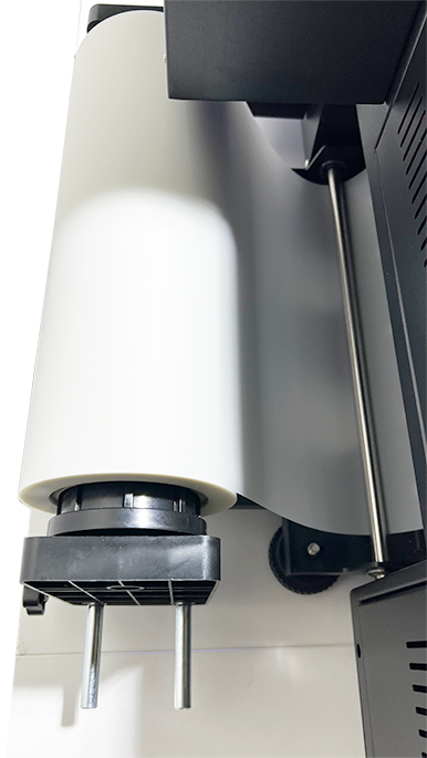
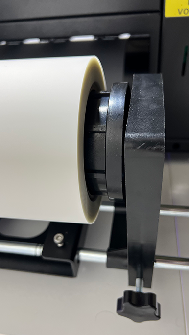
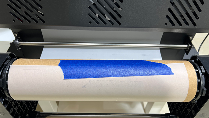
Install the left & right chucks onto the rods and mount the film roll’s core onto the chucks with the roll oriented so that the fill feeds from the top of the roll, passes under the tension bar, then feeds into the rear of the printer.
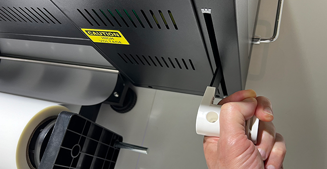
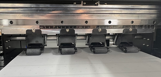
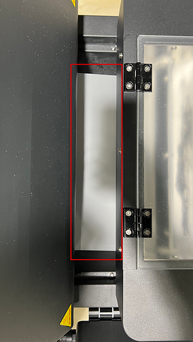
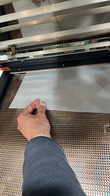
Lift the white-handled lever at the left-rear corner of the printer to raise the printer’s feed rollers, feed the film under the rollers and center it on the platen, then lower the lever to drop the rollers and secure the film in position.
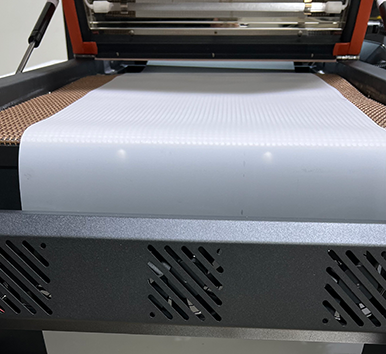
Hold the end of the film while releasing the rollers again with the lever, feed the film straight through the oven, and tape the end of it to the back of the oven until we’re ready to attach it to the takeup roll core.
Attaching the Takeup Roll Assembly
The following parts are used to assemble the DTF Mini’s takeup roll assembly:
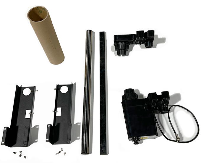
- Mounting brackets (2, left & right)
- Round crossbar
- Rectangular crossbar
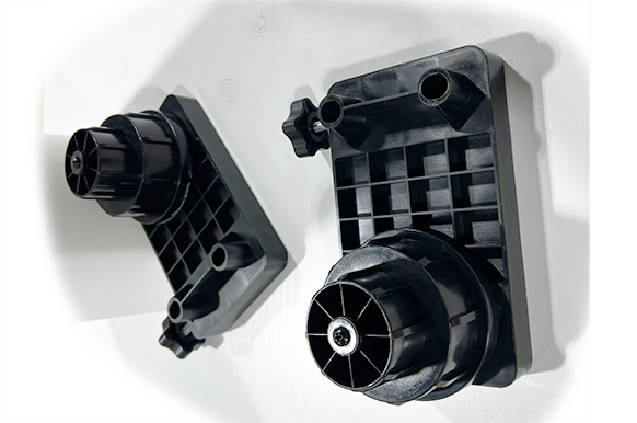
- Passive chuck (left)
- Motorized chuck (right)
- Empty roll core
- Philips head bolts (8)
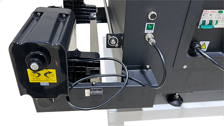
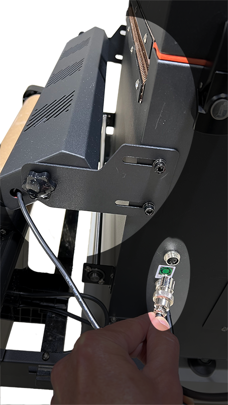
Mount the brackets to the sides of the DTF Mini oven, then insert the round & rectangular crossbars into their respective holes in the brackets. (You may need to loosen the preinstalled lock screws above the brackets’ holes if a crossbar can’t fit through easily.)
Temporarily pull the crossbars out of one bracket side and “thread” the chucks onto the round crossbar and mount it onto the rectangular crossbar with the motorized chuck on the right, then plug in the motor’s cable to the lower jack on the side of the oven.
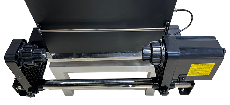
Finally, install the empty roll core onto the chucks, pull the film under the tension bar and core, then pull it taut and square it before taping the end of the film to the core.
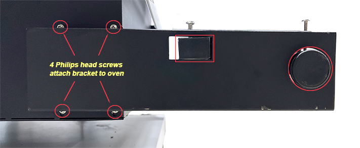
Attaching the Fan Assembly
The fan is packaged with its two mounting brackets and attachment hand-screws.
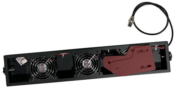
The four black Allen bolts used to attach the brackets to the oven frame are packaged in a separate bag with other misc. hardware.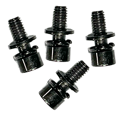
Attach the two brackets to the oven frame with the four Allen bolts, then attach the fan to the brackets and connect it to the upper jack on the oven as shown.
The Powder Keeper
The Omni DTF Mini is now set up and ready for your training session.
Not finding what you need?
You can contact our technical support team by sending an email to support@omniprintonline.com with your company name, contact name, phone number, printer serial number, and a quick description of how we can help you.
This will automatically open a support case for you in our ticketing system and a technical support rep will follow up with you shortly.