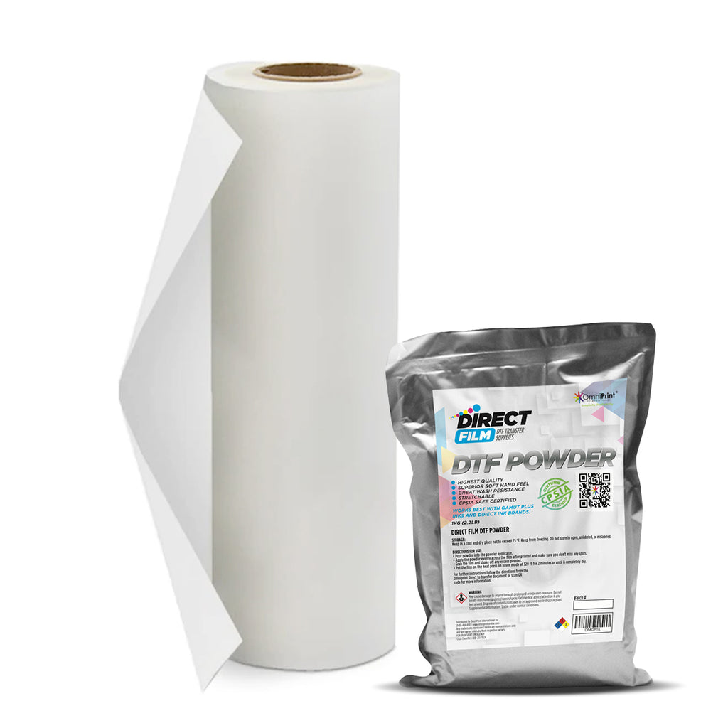
The OmniDTF system comes with everything you need to set up and start printing, including stands for both the printer and the dusting/curing oven assembly.
Review the below videos for help with the unboxing and setup process.
Unboxing the OmniDTF video
Setting up the OmniDTF video
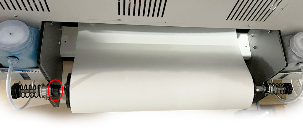
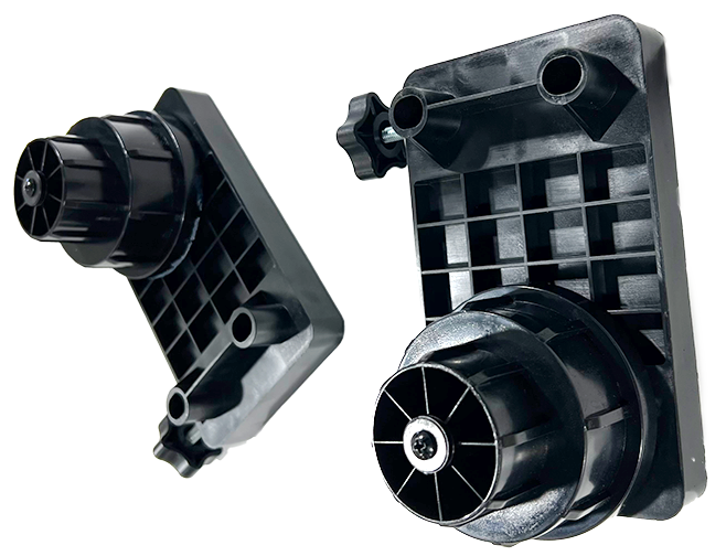
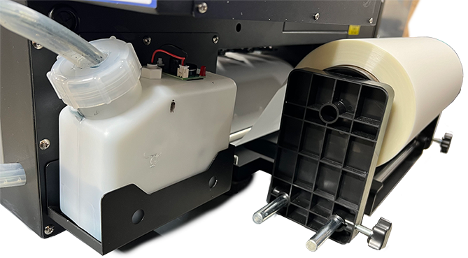
Printer Film Mount Detail
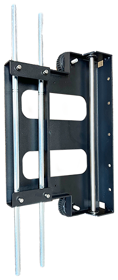
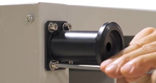
The film roll mounting hardware is not exactly the same on both the left and the right sides of the film roll.
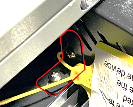
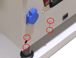
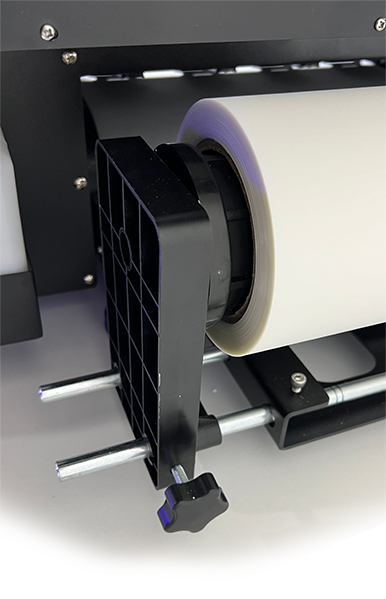
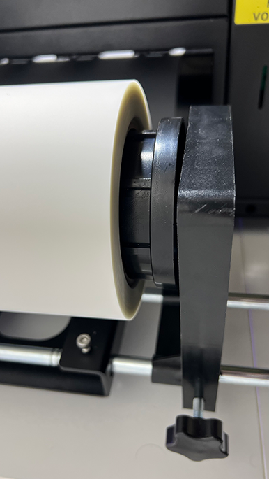
The left side includes a positional lock (circled in red below) that prevents the mounting hardware from shifting in either direction once it is properly positioned and tightened.
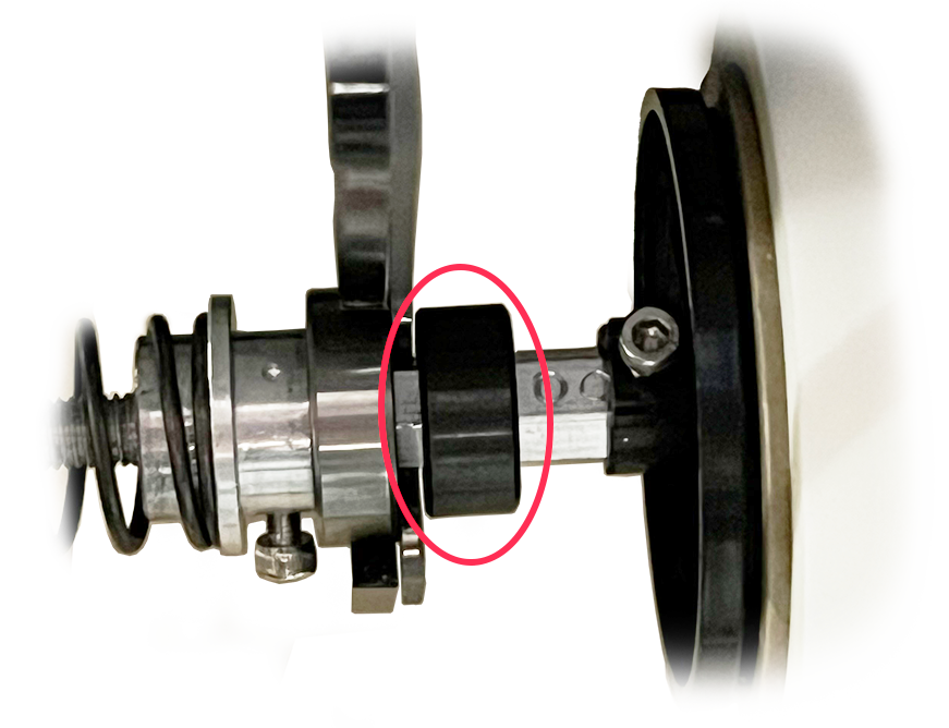
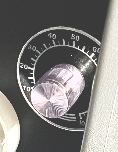
Here’s a closer look of the detail of the positional lock on the left side.
This positional lock is fixed with a screw once the film is confirmed to be properly aligned, using the line on the yellow alignment sticker near the back of the printers platen. Leave a small gap between the lock collar and the bracket that the assembly rests on.
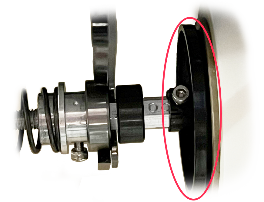
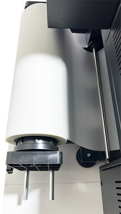
Once the setup and initial film alignment is completed, we don’t want to change the position of the film core’s mounting hardware, circled above.
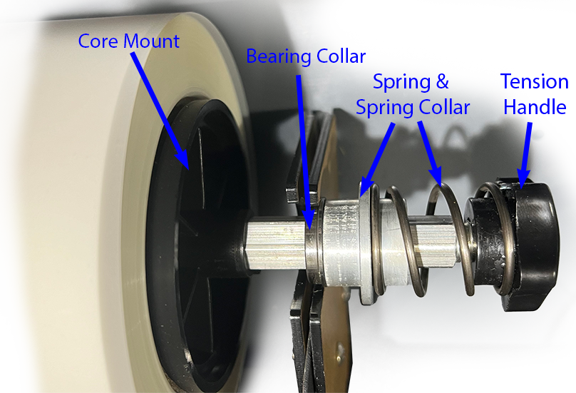
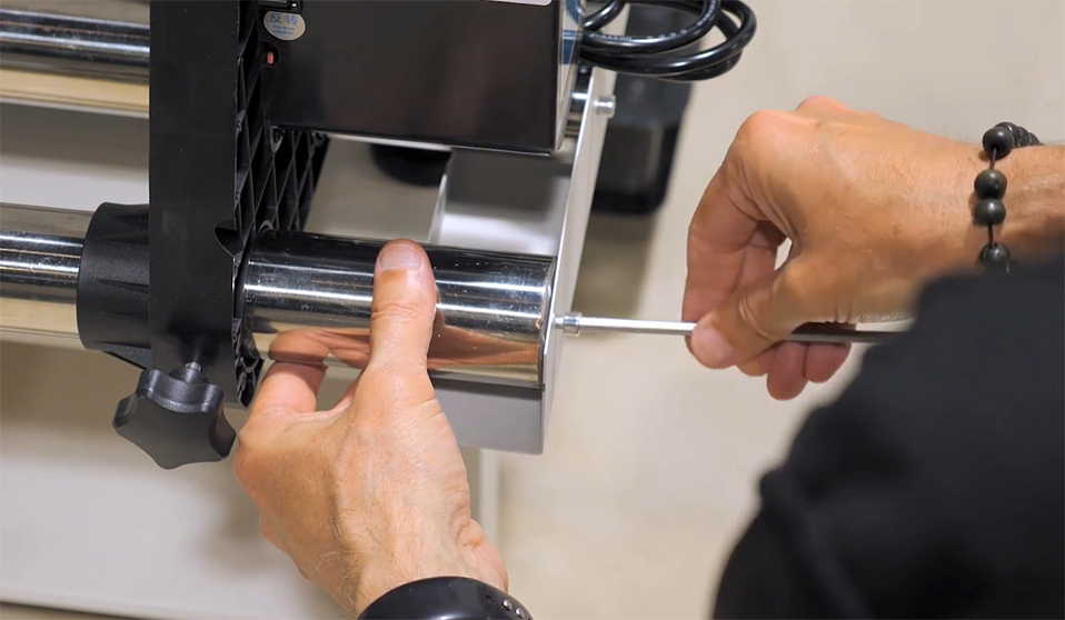
Work from the right side of the assembly to replace a film roll. Unscrew and remove the tension handle, then remove the spring, spring collar, bearing collar, and core mount on the right side of the film roll (when viewing from the rear of the printer), leaving the hardware on the left side in place.
Then reassemble after loading the new film roll.
Oven Film Takeup Roll Assembly Detail
The oven in the video below is nearly identical to the unit shipping with the OmniDTF. All instructions are 100% valid. The oven in this video is used with the Omni DTF Mini so is slightly smaller, but the main difference you may note is that the OmniDTF comes with an oven stand while the version in this video has feet and sits on a table.
Ease of setup is one of the benefits of the Omni DTF Mini system. In this article we’ll walk step-by-step through the process of getting your equipment unboxed, fully assembled, positioned, and loaded with film so it’s ready for your training session.
Preparing the Space
Power Requirements
The Omni DTF Mini’s oven must be powered from its own dedicated 20 amp circuit, while the printer’s more modest power requirements allow it to be used on circuits shared with other devices, including the air purifier. All of the equipment should be powered through surge protectors, rather than plugging directly into an outlet. As with any electronic equipment, damage caused by electrical storms or any irregular power problems is not covered by the warranty, since such damage is not due to a defect in parts or workmanship.
Equipment
AC Voltage
Peak Current
Omni DTF Mini printer
110-120 VAC
2.5A
Omni DTF Mini oven
110-120 VAC
19.5A
Air purifier
110-120 VAC
1.65A
As defined in the above specifications, the oven requires a dedicated 20 amp circuit and outlet, meaning that no other devices will be connected to any outlet on the same 20A circuit & breaker. It is recommended to have a qualified electrician install (or confirm the installation of) a 20A circuit with suitable gauge wiring and that no other outlets share the same circuit.
Space Requirements
It’s necessary to be able to move around the printer and oven to ease doing things like loading new rolls of film, circulating the white ink, cleaning the undercarriage, refilling the powder hopper, and removing completed prints.
We recommend leaving about 18 inches around each side of the equipment, though 12 inches may work for some customers.
Unboxing & Setup
Demonstration Video
Positioning & Leveling the Printer and Oven
When selecting a desk or bench for the printer and oven, keep in mind that the top surface of the oven’s table or bench should be 16″ to 22″ below the top surface of the printer’s table. This provides a sufficient drop from the printer’s platen to the oven’s film entry slot to support the film advancing consistently. Greater distances may result in poor transfers and durability issues due the ink drying too much before powder is applied.
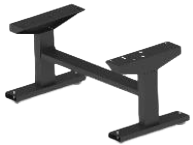
Note the following minimum specifications when selecting or constructing a table for the oven: 2.5′ (30 inches) W x 3′ (36 inches) L, with a 150 lb. weight capacity. The minimum & maximum height will depend on the height of the table that the printer is on.
Ensure that the top surface of the oven’s table is 16″ to 22″ below the top of the printer’s table to support proper film movement and powder adhesion.
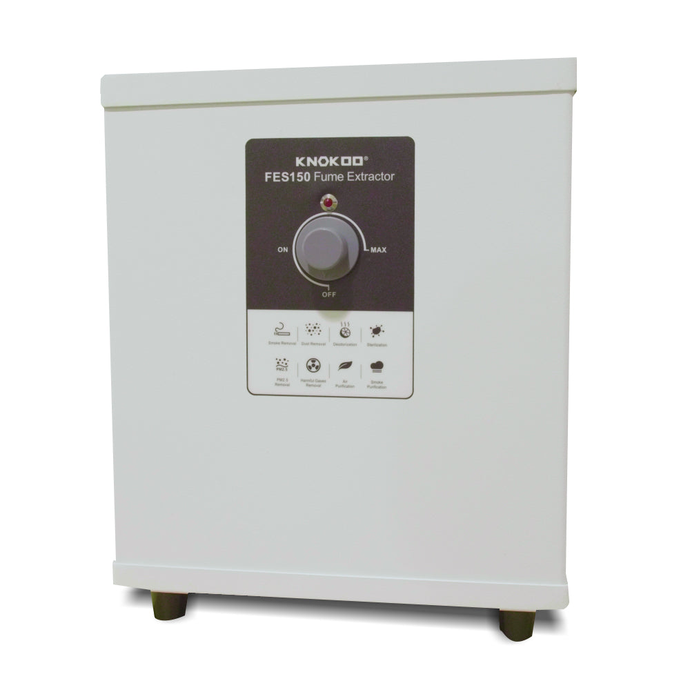
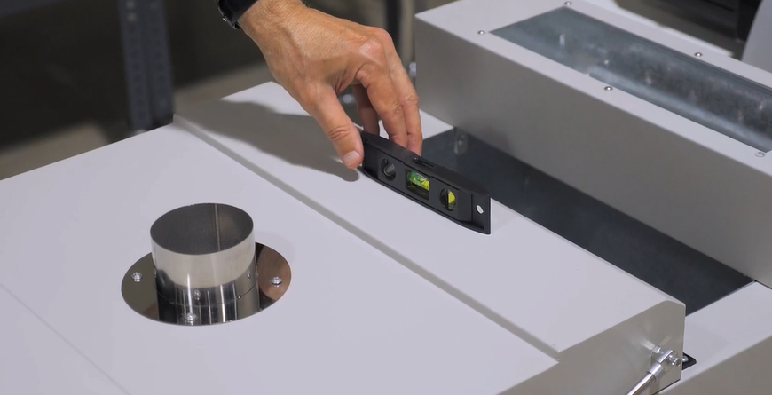
The printer’s four feet are mounted onto bolts which can be rotated to lengthen or shorten their length.
Adjustable height feet on the DTF Mini printer & film roll bracket. The printer feet are circled in red and the film roll bracket feet are inside green rectangles.
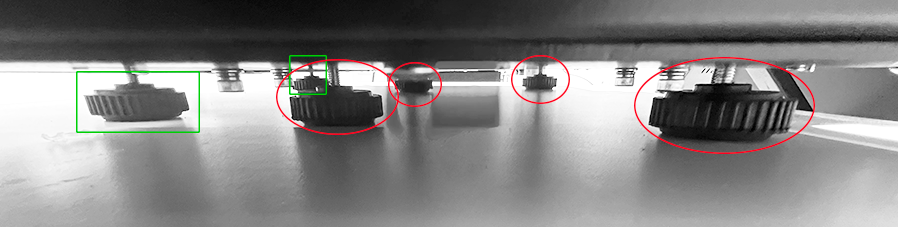
These should be adjusted so that the printer is level, while the feet supporting the film roll bracket (also shown below) should be at their minimum length.
Checking the level on the DTF Mini printer’s film roll bracket.
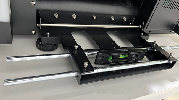
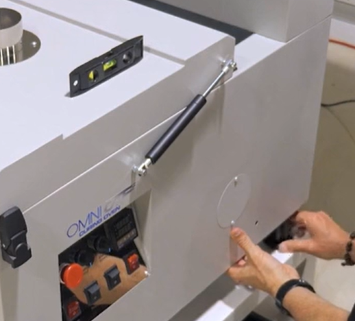
While leveling, keep in mind that the printer’s feet should elevate the bottom of the printer at least 1″ above the surface of the table or bench that it rests on.
Elevate the printer’s base at least 1″ above the table top.
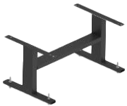
The oven assembly’s feet also have adjustable length bolts for leveling the equipment.
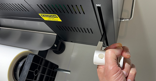
Removing the Carriage Lock Bracket
The printhead carriage is bolted to the frame to prevent potential damage due to motion during shipment. Remove the locking bracket before connecting the power and turning on the printer.
The bracket attaching the left side of the printhead carriage to the carriage frame is removed by taking out the two screws that hold it in place.
Carriage lock bracket and screws with a warning tag.
Failure to remove the carriage lock bracket before applying power to the printer may damage the printer’s electronics. Remember that damage caused due to improper use is not covered by the warranty.
Final Oven Assembly
Now we’ll complete the oven setup by attaching the adjustable-length legs & feet, the takeup film roll assembly, and the powder catch try (aka recycle bin).
Attaching the legs, center & level the oven
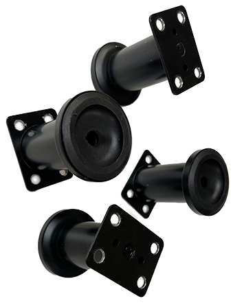
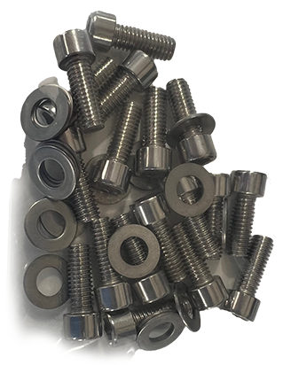
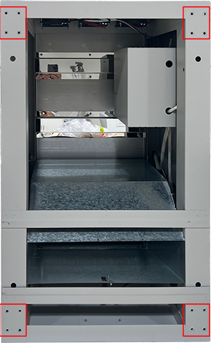
There are four adjustable-length legs & feet. Each is attached to a corner on the bottom of the oven with four M5 bolts & washers.
After attaching the adjustable legs, position the oven upright, squared with the printer in the prepared space, and centered on the printer’s platen.
Adjust the length of each leg as needed to level the oven side-to-side and front-to-back.
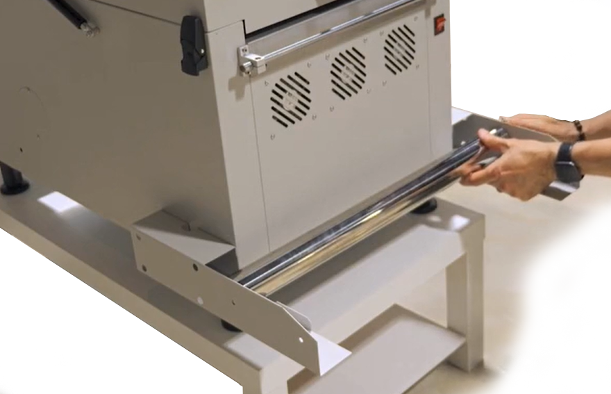
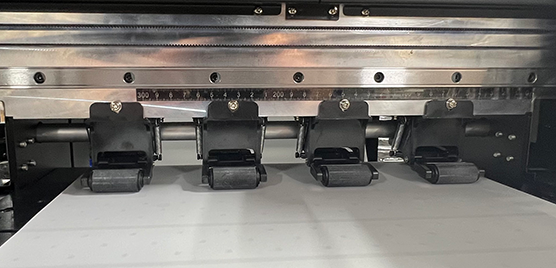
Attaching the takeup roll assembly
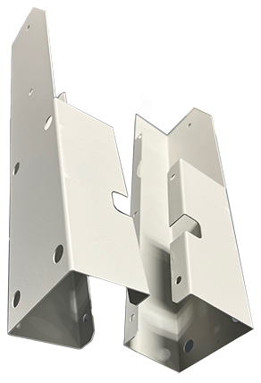
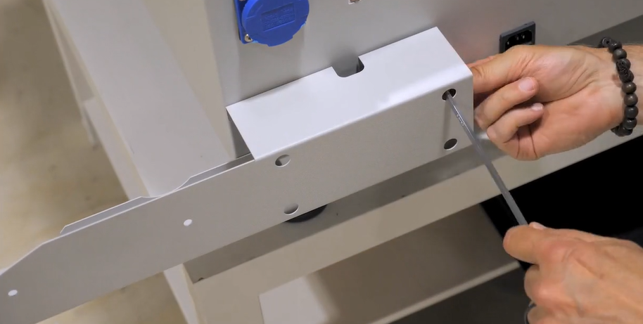
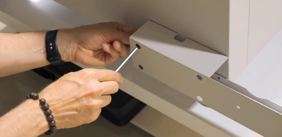
Attach the left and right brackets using the bolts already in the oven. Remove the bolts and reattach them with the brackets.
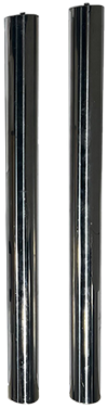
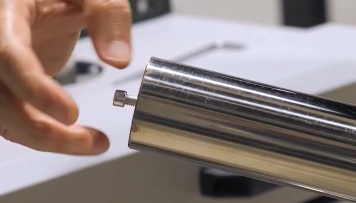
The chrome-plated crosspiece cylinders have their attaching bolts screwed into each end. Remove the bolts and install one of the crosspieces onto the brackets in the position closest to the oven, then attach it by reinstalling the removed bolts.
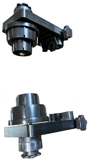
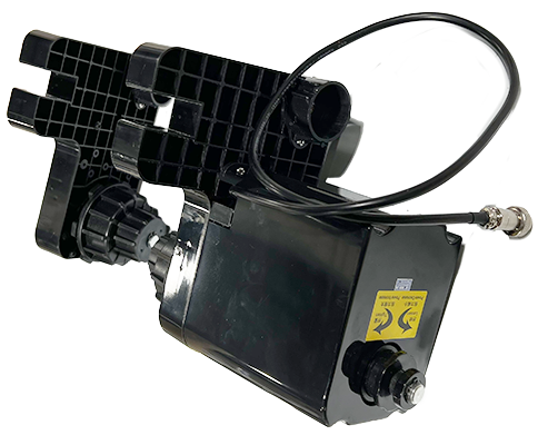
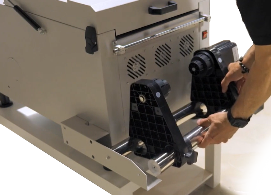
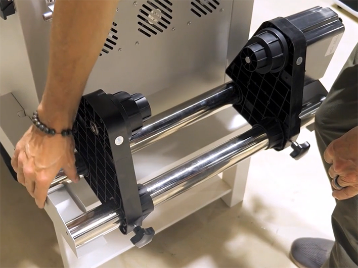
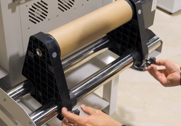
Thread the next crosspiece through the round holes of the two “chucks”, with the motorized chuck positioned on the right and the passive chuck on the left.
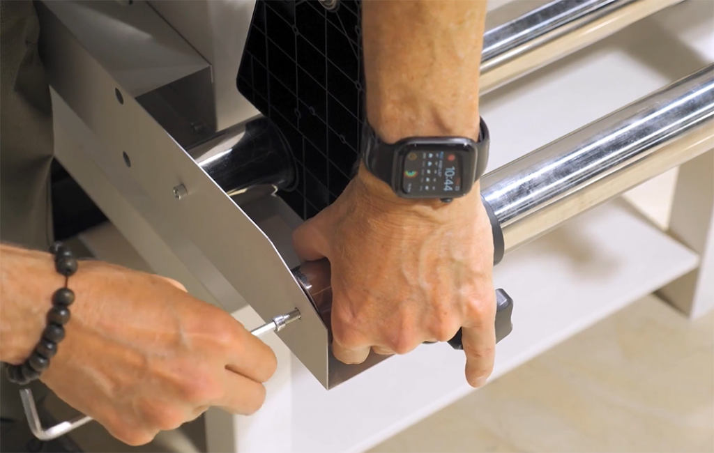
Then slide the U-shaped openings onto the previously installed crosspiece, drop the new crosspiece into place on the bracket, and attach it with its bolts.
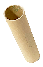
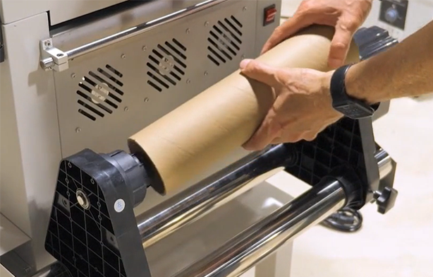
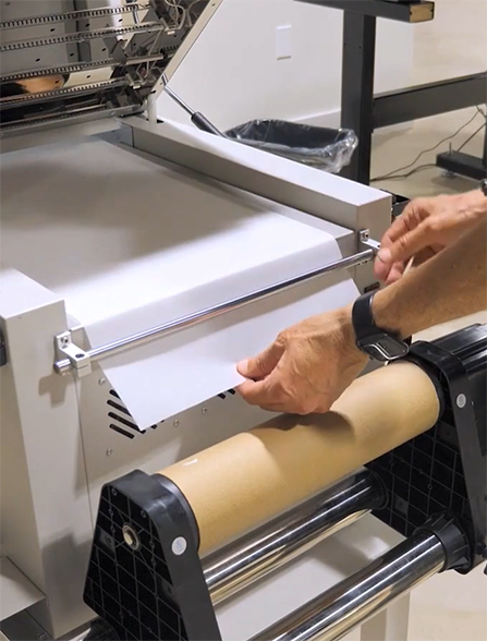
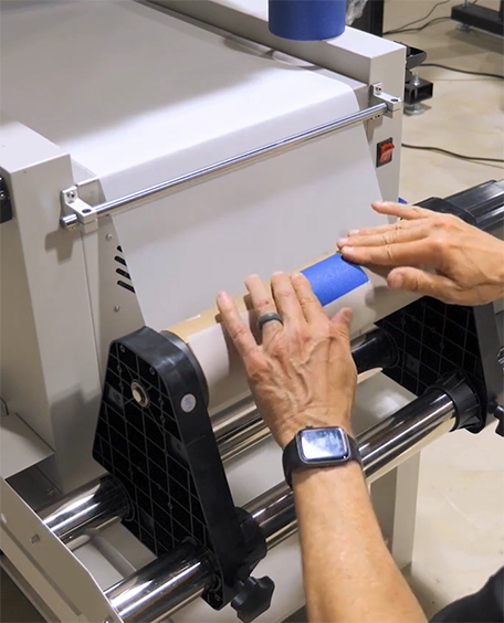
Mount the empty cardboard core for the takeup roll, center it on the oven, and lock its position.
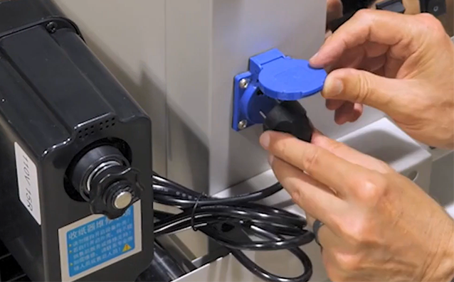
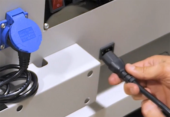
Plug in the takeup roll motorized chuck and the main oven power cables.
Put the takeup motor’s directional power switch in the up (clockwise) position.
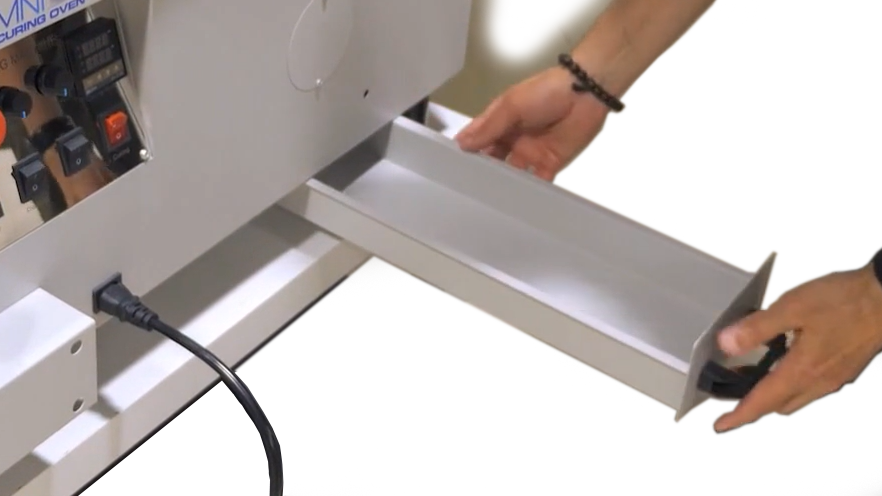
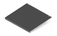
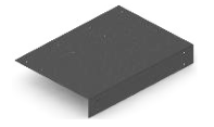
Install the powder catch tray (aka the “recycle bin”)
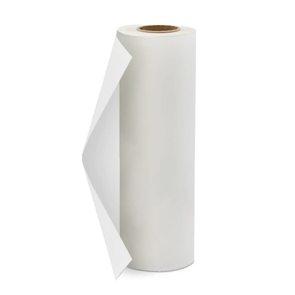
Loading the Film
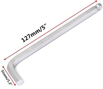
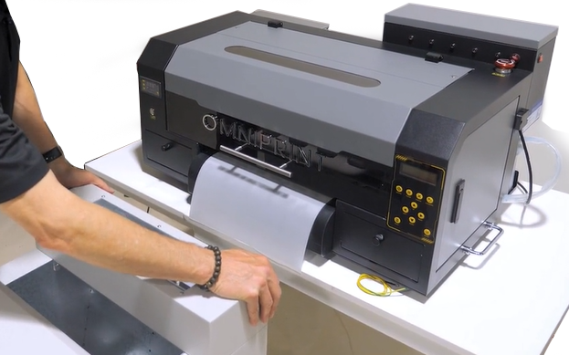
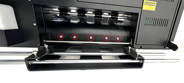
First, attach the factory-assembled film roll support bracket to the back of the printer. Remove the five Allen head bolts, line up the bracket with the holes those bolts were removed from, then reinstall the bolts to attach the bracket.
DTF Mini printer with the film roll bracket attached by 5 bolts.
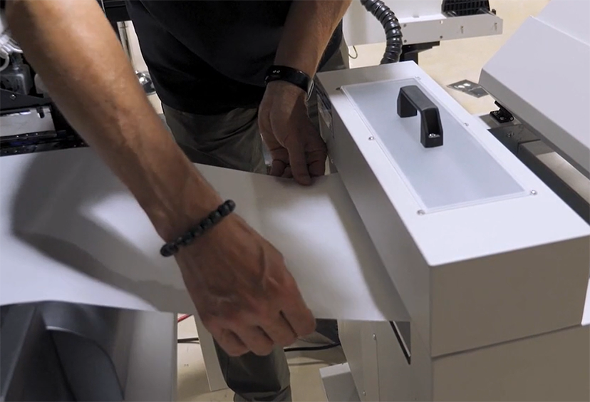
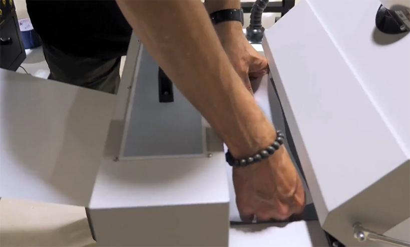
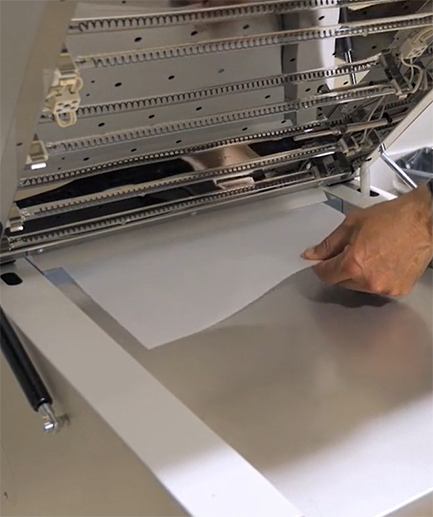
Install the left & right chucks onto the rods and mount the film roll’s core onto the chucks with the roll oriented so that the fill feeds from the top of the roll, passes under the tension bar, and then feeds into the printer.
Lift the white-handled lever at the left-rear corner of the printer to raise the printer’s feed rollers, feed the film under the rollers and center it on the platen, then lower the lever to drop the rollers and secure the film in position.
Hold the end of the film while releasing the rollers with the lever. Then feed the film straight through the oven, under the tension bar, under the core, and tape the end to the core.
Follow the steps demonstrated in the below video or described in the following text each time you start up the Omni DTF Mini to ensure that your first print and every print is top-quality.
Video Demonstration
Startup Summary
Check the level of the waste ink bottle and empty as needed.
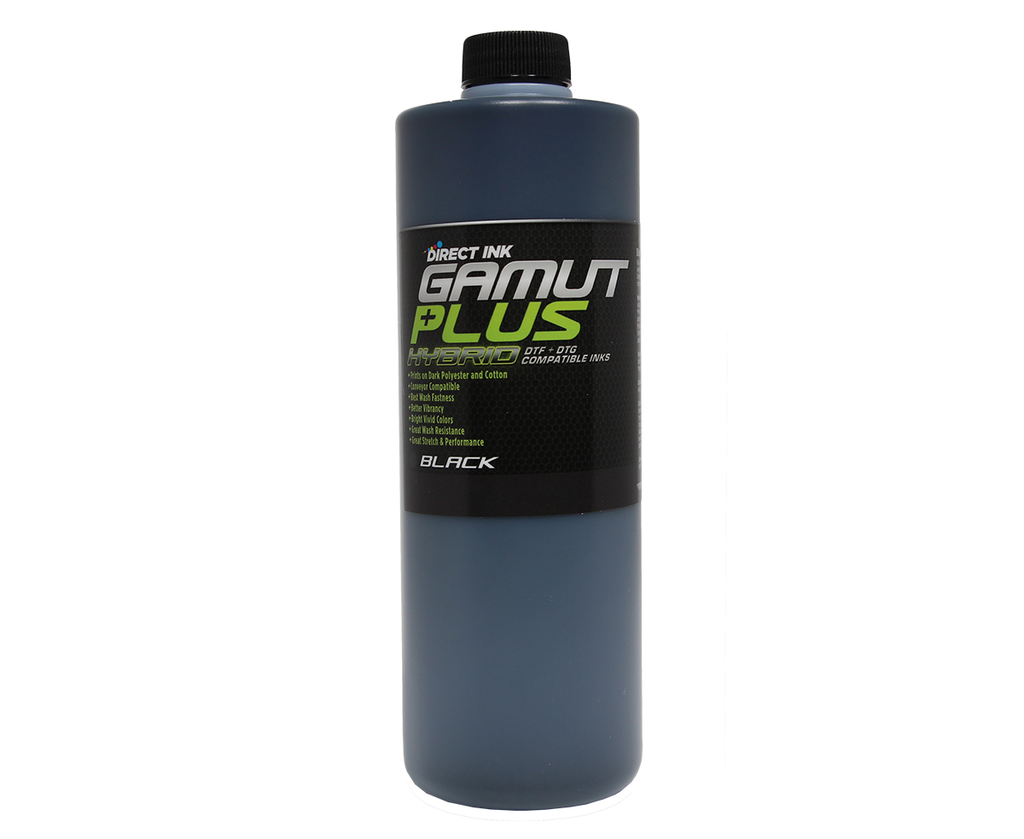
Check the level of the ink bottles and refill as needed.
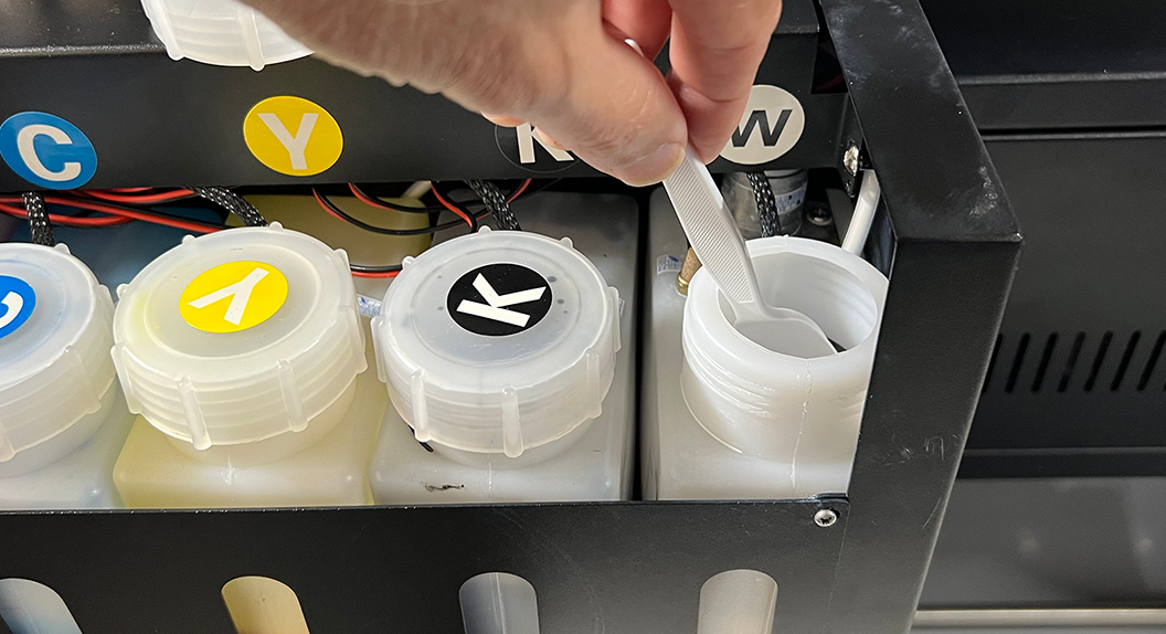
Stir the white ink manually, especially at the bottom of the bottle.
Turn on the printer power
The printer will stir the white ink for an additional minute. Note that this automated stirring is in addition to the manual stirring done in the previous step.
Rotate the white ink circulation pump control fully clockwise.
The white ink will circulate for 5-minutes.
Turn off the white ink circulation switch after it completes its 5-minute cycle.
Open & reposition the ink clips.
Run two head cleanings.
Print and evaluate a nozzle check.
Run additional head cleanings if needed to acheive a 90% complete or better nozzle check test pattern print.
Daily Startup Illustrated Details
Check the level of the waste ink bottle and empty as needed.
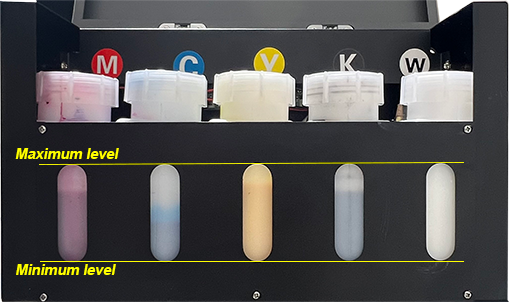
Check the level of the ink bottles and refill as needed.
It’s important keep the ink level between the minimum & maximum levels shown above to maintain good ink flow and avoid the risk of getting air into the ink lines. It’s recommended to also equalize the levels.
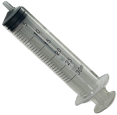
Stir the white ink thoroughly, especially at the bottom of the bottle where the automated stirring mechanism cannot reach, using a non-porous and non-metallic spoon or stirring stick. A non-porous plastic spoon, knife, or stirring stick will work fine. Just be sure to remove the stirring tool when finished stirring. Don’t leave it soaking in the ink.
Turn on the printer’s power.
The printer will automatically stir the white ink for 1-minute immediately after being turned on.
Open the printer’s right-side access panel door and rotate the white ink circulation pump control to its fully-clockwise position.
The white ink will automatically circulate for 5-minutes immediately after the white ink stirring cycle is completed.
Turn the white ink circulation controller to its full counterclockwise position (OFF) after its 5-minute cycle completes and before proceeding to the next step.
Failure to turn off the circulation before opening the white ink clips can cause waste ink and air to be pulled into the white ink system. If this happens a significant amount of white ink will be wasted to prime the air out of the white ink system.
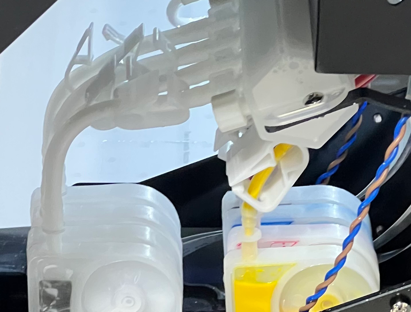
Open the ink clips, after turning off the white ink circulation controller.
Reposition the ink clips after opening them so they will clamp in a different position when closed.
Roll the ink tube between a thumb and finger to round out the ink tube if it is somewhat collapsed where it had been clipped.
Run two head cleanings.
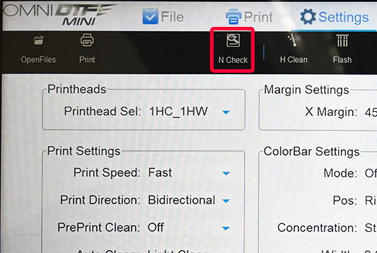
Print a nozzle check from the Omni DTF Mini UI software.
If each channel of the nozzle check (cyan, magenta, yellow, black, and 4 white boxes) is 90% complete or better, you are ready to turn on the oven and begin producing prints.
Run additional head cleanings and nozzle check prints if needed to acheive a 90% complete or better nozzle check test pattern print on each color channel.
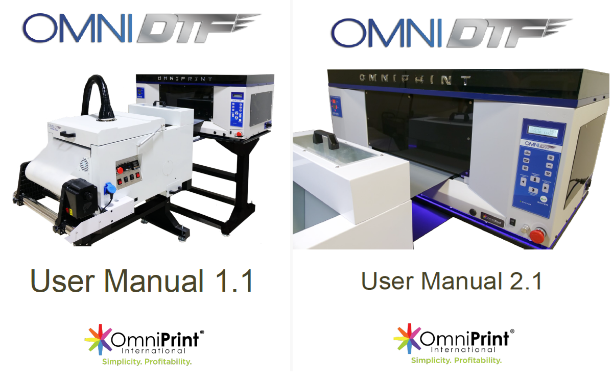
Download or view an OmniDTF User Manual from the below links.
The fastest way to identify which manual version is right for you is to identify whether or not your waste ink bottle is mounted on the back of the printer (original version) or to the right side of the printer stand (2.0 version).
The OmniDTF has a robust set of hardware controls, making it simple and convenient to operate most routine functions directly from the printer itself. Here’s a brief rundown on the position and function of each of these controls.
Printer Controls
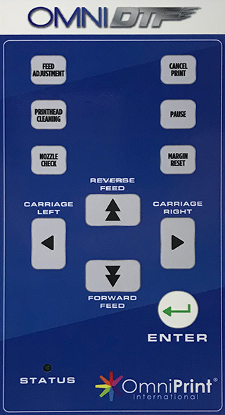
Control Pad
This is the set of pressure-sensitive buttons on the front of the printer, to the right of the platen.
Feed Adjustment: Adjust vertical feed between print passes (use only as directed by Omniprint staff.)
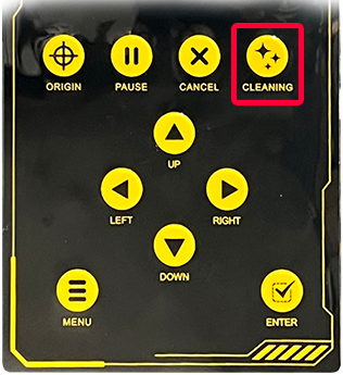
Printhead Cleaning: Run a Light printhead cleaning on both printheads.
Nozzle Check: Print a test pattern to confirm that ink flow is optimal and ready to deliver quality prints.
Cancel Print: Stop printing and remove the remaining print job from the printer’s memory.
Pause: Temporarily stop printing. Pushing Pause a second time will prompt you to continue printing.
Margin Reset: Change the right margin from the default of 10mm (use only as directed by Omniprint staff.)
Carriage Left / Carriage Right: Move the printhead carriage to the left or to the right of its current position. Hold the button for continual movement.
Reverse Feed / Forward Feed: Feed film forward (toward the front of the printer) or backward.
Enter: Submit responses to prompts on the display panel or move the printhead carriage to the Home position (above the capping stations) if there is no prompt
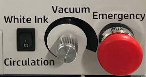
Front Panel Switches
There are three switches positioned directly below the Control Pad. Two of these can generally be thought of as set it and forget it, and the third is essentially an emergency kill-switch. Here are the details.
White Ink Circulation: When toggled to the ON (1) position, white ink is circulated for 1-3 minutes.
Vacuum: This rotary switch turns on and adjusts the suction of the platen’s vacuum. We recommend turning it on and adjusting it to its lowest level for optimal film feeding and platen temperature stability.
Emergency: This red “kill” switch immediately shuts off power to the printer’s electronics when depressed. Once depressed this latching switch will remain engaged and prevent the printer from operating until it is rotated clockwise about ¼ of a turn. It will then pop out and normal operation will be restored.
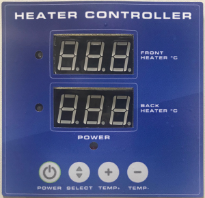
Heater Controller
The Heater Controller is used to adjust and provide status of the OmniDTF printer’s two film heaters. One heater sits behind the platen, to preheat the film as it enters the printer chassis. The second one is under the platen, to keep the film warm as it is being printed on. Heating the film helps the ink set quickly, so the white layer can be applied just seconds after the color layer.
Exceeding the preset temperatures of 40 degrees Celsius for the Front Heater and 50 degrees Celsius for the Back Heater may result in damage to the printheads and/or printer. Damage due to misuse voids the warranty.
Front Heater & Back Heater: The Front Heater and Back Heater numeric displays report each heater’s current temperature in Celsius. When changing the temperature setting, the displays show the changes being selected.
Power: The Power button turns both heaters ON or OFF, toggling their current status. The heaters automatically turn off when the printer is switched off. If the heaters were on when the printer was switched off then they will automatically turn back on when the printer’s power is turned on.
Select: To change a temperature setting for a heater, that heater must first be selected by pushing the Select button, after which the numeric display of the currently selected heater will flash. The first press of the Select button selects the Front Heater. A second press selects the Back Heater. A third press of the Select button exits the temperature adjustment mode.
Temp: The Temp (+) and Temp (-) buttons are used to raise or lower the temperature setting of the currently selected heater.
Dust-Curing Machine Controls
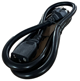
The Dust-Curing Machine has its own power cord and switch, so is plugged into a separate outlet from the printer. While the two pieces of equipment are powered and controlled independently, they form a single, complementary system.
Most of the controls on the Dust-Curing Machine are found on a single control panel on the right side of the equipment. We’ll detail each of those first and then move on to the exceptions.
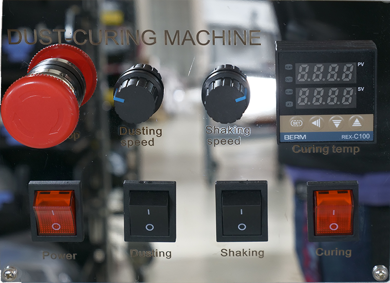
Control Panel
Here you’ll find switches for Power, Dusting, Shaking, Curing, and an Emergency off switch. In addition to these switches, there are also granular controls for setting the dusting speed, shaking speed, and curing oven temperature.
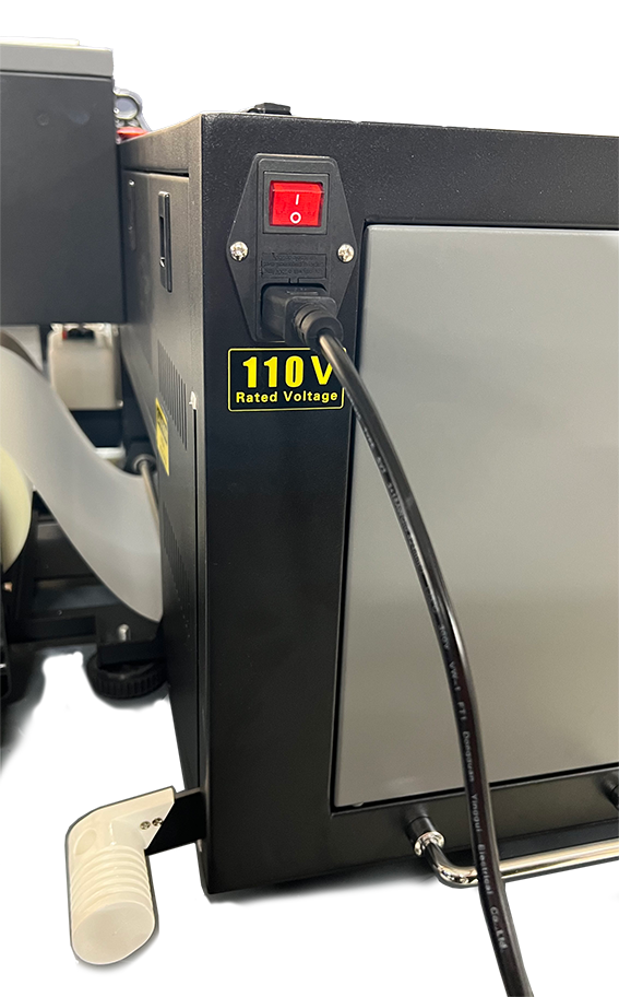
Power Switch
The Power switch in the lower-left corner of the Control Panel is the master power for all other switches and functions of the Dust-Curing Machine. When this switch is OFF, all other switches and controls of the Dust-Curing Machine are inoperable because there is no power being supplied to any part of the unit.
Emergency Switch
The round, red Emergency button above the Power switch will immediately shut off power to the Dust-Curing Machine when depressed.
This is a “latching” switch which, once depressed, will prevent the Dust-Curing Machine from operating until the switch is released. If you ever find that the Dust-Curing Machine won’t turn on from it’s power switch, make sure this switch is not depressed.
To release the switch, rotate the handle clockwise for approximately ¼ turn. Once the switch is rotated clockwise, a spring will push it back out and power will then be restored to the Dust-Curing Machine if, or as soon as the Power switch is in the ON position.
Dusting Switch & Speed control
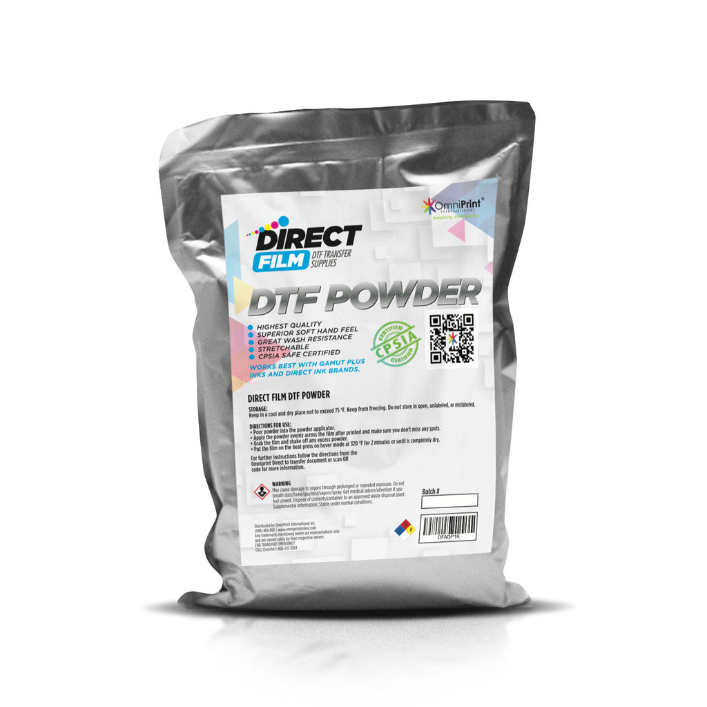
There are two Dusting controls used to add DTF Powder onto the film as it passes through the powder application chamber.
Dusting switch: This switch toggles the power to the rotating Dusting blades in the DTF Powder Feeder to sweep powder into position to cascade onto the film through narrow slits in the bottom of the powder feeder.
Dusting Speed dial: This dial is used to adjust the rotational speed of the DTF Powder Feeder. The further it is turned clockwise the faster the feeder will rotate and sweep DTF Powder into position to be dusted onto the film.
Shaking Switch & Speed control
There are two Shaking controls used to remove excess DTF Powder from the film after it has been applied by the Dusting feature.
Shaking switch: This switch toggles power to the rotating Shaking spindle with short plastic straps that shake the film as they rotate, shaking any excess DTF Powder back onto wet ink or into the Powder Recycle Bin.
Shaking Speed dial: This dial is used to adjust the rotational speed of the Shaking spindle. The further it is turned clockwise the faster the straps will shake the firm to knock excess DTF Powder loose.
Curing Oven Temperature
There are two controls for the Curing Oven. Remember that using a temperature that will effectively cure the ink and melt the DTF Powder is an important part of the DTF production process. We recommend starting with a setting of 120 Celsius and adjusting from there as needed.
Curing switch: The curing switch turns power for the Curing Oven and the Curing Temp Controller ON and OFF.
Curing Temp Controller: The Curing Temp Controller is used to set and monitor the oven temperature, using four buttons and two numeric displays.
When the Curing power is switched on, the upper display shows the current oven temperature, and the lower display shows the temperature setting.
Changing the temp setting
Set button: Push and hold the Set button until the lower numeric display begins to flash.
◄ button: When in the temperature setting mode (having been activated by the Set button), the temperature setting display shows a cursor in the rightmost column of the setting number.
We recommend making temperature adjustment in 5-degree increments, so for most temperature changes you’ll want to adjust from this rightmost position. To change the setting in increments of 10’s, use this button to move the cursor one digit to the left – to the 10’s position.
▼ button: Use this button to reduce the temperature setting at the cursor position.
▲ button: Use this button to increase the temperature setting at the cursor position.
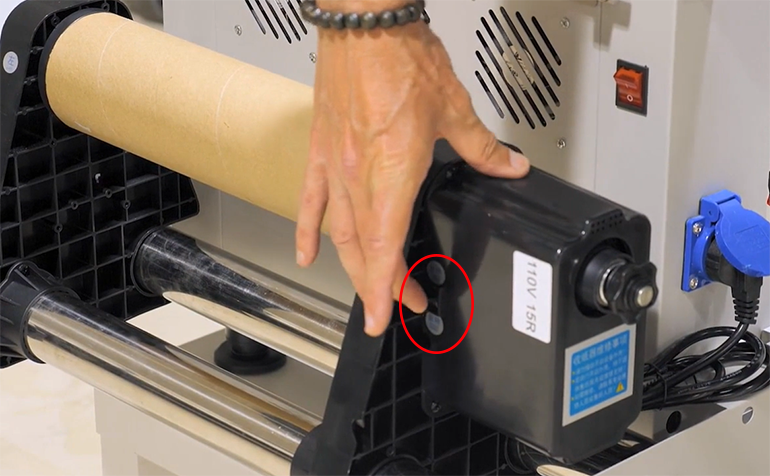
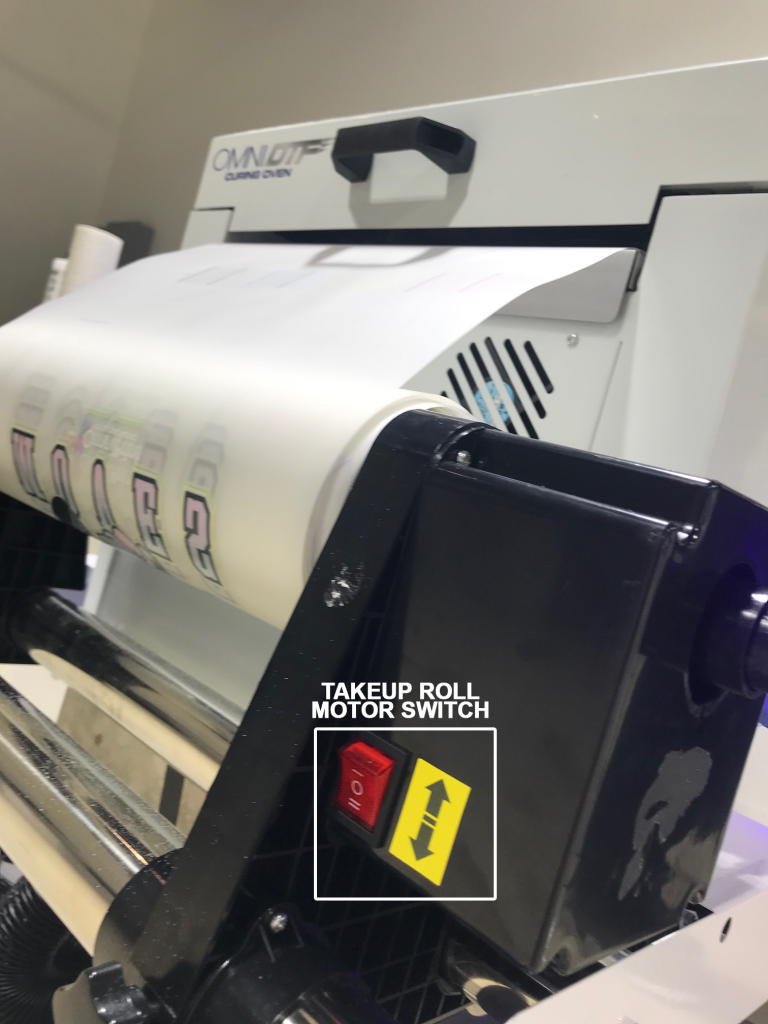
Take-up Roll Motor Switch
This 3-position switch is set to the down position to enable the motor to rotate the take-up roll counter-clockwise (from the perspective of the side of the Dust-Curing Machine controls.) The center position turns the motor off, and the top position is for reverse feeding film backwards, toward the oven and printer.
Remember that the Power switch on the Dust-Curing Machine turns on & off the power to all features of that equipment. If you prefer you can leave the other switches on and just use the main Power switch.