If ink is dripping from a printhead this indicates that the bottom of the printhead (the nozzle plate) has been soaking in ink (or an inky cleaning solution) that’s filled the capping station.
We always want to run at least one head cleaning during the startup process and immediately after “priming” or “loading” ink. The head cleaning process uses the wiper blade to wipe any ink off of the nozzle plate and drains any fluids from the capping station to the waste ink bottle.
There’s one more possible cause for excessive ink in the capping stations aside from wet capping and priming ink, this next one being specific to an available but not recommended setting on the OmniDTF.
OmniDTF Flash Feature
The OmniDTF printer includes a Flash feature which causes the printheads to spray a small amount of ink into the capping stations periodically, as a nozzle clearing function. OmniPrint disables this feature during the manufacturing process and recommends that it be kept OFF to conserve ink and to prevent the capping stations from filling with ink while printing.
To determine if the Flash feature is enabled, check the second (from left) icon in the lower-left corner of the OmniDTF UI software. If it is green then Flash is ON. If it is white then Flash is OFF.
Flash ON
Flash OFF
So we want the icon status in the lower-left corner of the OmniDTF UI software to look like this:
Turning OFF Flash
If Flash is ON, turn it OFF by clicking on the Flash icon on the toolbar running across the top of the OmniDTF UI software.
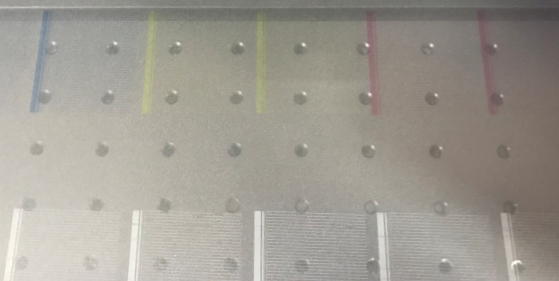
“Banding” refers to the appearance of visible horizontal lines or streaks on a printed image that appear in the left & right direction of printhead carriage movement. Rather than a streak of white or colored ink smearing across film that would indicate a head strike, banding appears as inconsistent ink coverage (see example photo below).
Banding example
Most Common Banding Solution
When troubleshooting a banding problem the first step is to print a nozzle check. This is done to distinguish between ink flow issues from mechanical or configuration issues.
If the nozzle check isn’t looking great when you experience banding there’s a good chance the issue can be resolved by simply running a printhead cleaning. This is because banding can occur during longer print jobs due to ink mist from the printing process building up and beginning to dry on a printhead’s nozzle plate. So if you’re currently experiencing a banding problem, run a nozzle check now and follow that with printhead cleanings, as needed, to resolve a poor nozzle check.
OmniDTF nozzle check example
Lower humidity environments will typically require more frequent head cleanings since the ink will be more prone to drying on the nozzle plates.
If head cleaning doesn’t result in getting a good nozzle check, something may be limiting the ink flow that will require more troubleshooting to resolve, which we’ll get into momentarily.
But first, if you are getting a good nozzle check but still have banding, there are a few software settings to check and confirm that it is optimized to provide great quality prints.
Let’s look at those software settings now.
OmniDTF UI Software Settings
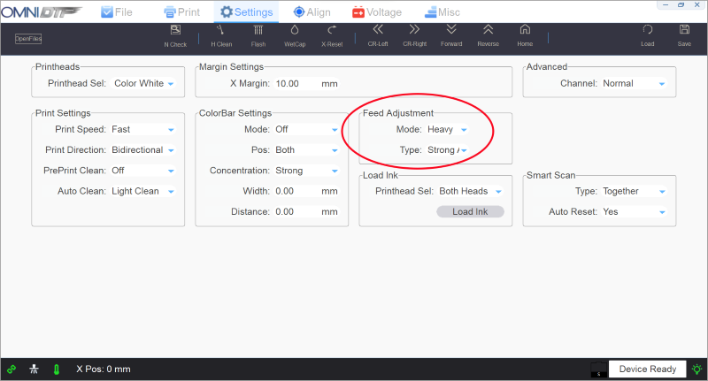
OmniDTF UI Settings screen, Feed Adjustment
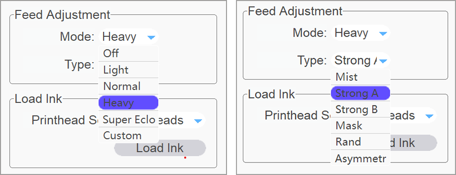
On the Settings tab of the OmniDTF UI software, check the Feed Adjustment section’s Mode and Type options. We want Mode set to “Heavy” and Type set to “Strong” for the best results.
Feed Adjustment recommended settings
These are the normal, default settings of a new OmniDTF UI software installation, and it’s a super easy fix if your settings aren’t right.
Print Pro Environments & Printing Resolution
Another possible software solution for light banding is to increase the ink density that you’re printing by selecting a higher resolution Environment when setting up your Layouts in Print Pro DTF.
If currently using the 720×1800 Environment then try 720×2400, or if using 720×2400 then try 720×3600.
With those software settings out of the way, let’s dig into potential ink flow causes and solutions.
Ink Flow Limiting Causes & Solutions
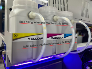
Low ink level in ink bottles This is a simple but often overlooked fundamental cause of color dropouts and banding.
It’s important to keep an eye on ink levels and make sure they never drop below their defined minimum levels (see below image) before being refilled to ensure consistent ink flow.
OmniDTF ink bottle minimum and maximum levels
Air pockets or bubbles in ink lines All of the components in the printer’s ink flow path are designed to maintain an air-tight system. In normal operation, with proper maintenance, there should be no air in the ink lines.
If you find air pockets or bubbles in one or more ink lines, use the Load ink feature for the white or color (or both) printheads to “prime” out the air pockets. As always, keep an eye on the waste ink bottle when using the Load ink and Printhead cleaning features and empty it as needed to ensure that it doesn’t overflow.
Clogged, damaged, or worn out damper Dampers are consumable parts whose functions are critical to good ink flow. If a) you’re getting bad or inconsistent successive nozzle checks that aren’t resolved with head cleaning, b) your ink levels are good, and c) there’s no visible bubbles or air gaps in your ink lines (or air keeps returning to the lines after priming it out) then it’s recommended to contact OmniPrint technical support about replacing the damper for the problem channel(s).
There’s a link at the bottom of this page to another knowledge base article with details about dampers, in case you’re interested in more details about 4 things that dampers do to help maintain good ink flow.
Clogging in ink lines Normal use and maintenance will prevent clogging of the ink lines, but excessive air in the ink lines or longer-term idle periods with no ink flow can result in dried or drying ink clogging the ink lines.
If your printer will be idle for more than 3 weeks (even if wet capped) we recommend contacting OmniPrint technical support to schedule an appointment and prepare the printer for extended downtime or storage.
Routine Preventative Maintenance Finally, we recommend cleaning out your white ink bottles at least once per year to remove any sediment that may be collecting there due to the heavier pigment needed to product white ink.
Likewise, don’t forget to regularly agitate the white ink bottles to keep the white ink well-mixed and circulate the white ink during your routine startup process.
As mentioned in the OmniDTF System Shutdown article (linked at the bottom of this page), performing proper maintenance and wet capping the printer when shutting it down is critical to maximizing the service life of your printheads, capping stations, and wiper blade.
The process detailed in that article requires using the OmniDTF UI software to wet cap the printheads after completing the shutdown maintenance. Moving the carriage away from its home position can be done from the printer’s control pad or the OmniDTF UI program.
But what if you experience a power failure or your PC has lost its ability to communicate with the printer for some reason?
In the below video and the following instructions, we explain how to manipulate the capping station platform and the carriage to allow performing shutdown maintenance and wet capping the printer manually in the event of a power failure or any situation that prevents normal use of the controls and software.
Turn off the power switch on the printer before proceeding if you have lost power. This is done to ensure that the printer doesn’t suddenly come back on if power is restored. Mechanical movement during the printer’s initialization could injure someone in the middle of performing maintenance and also damage the printer. It is also recommended to turn off the curing oven to ensure that it doesn’t come back on and heat up while unattended.
Demonstration video
Your PC Can’t Wet Cap the OmniDTF
If you have not lost power and the printer’s control panel is working fine but you can’t complete the wet cap process from the OmniDTF UI software on your PC for any reason, follow the usual shutdown procedure until it’s time to click on the software’s WetCap icon. At that point, follow the instructions near the end of this article for Manually Wet Capping the Printheads.
The Printer Has No Power
If you have lost power, first make sure the Emergency button hasn’t been accidentally depressed by rotating it about ¼ turn clockwise. That will release the button and restore power if it had been depressed.
If the Emergency button was not depressed, either power is no longer being provided by the outlet or the printer’s power system needs troubleshooting. In either case, we want to ensure that the printer’s carriage will not move if power is restored while you’re working on it by turning off the printer’s power switch. Optionally, you can also unplug the power cable.
The Dust-Curing Machine’s master Power switch or its oven’s ‘Curing’ switch (for power to the oven) should also be turned off, to prevent it from coming back on while potentially unattended when power is restored.
Manually Releasing and Undocking the Printhead Carriage
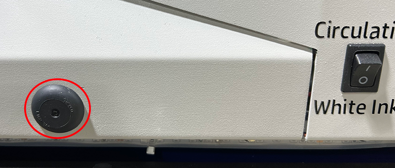
Remove the small, black rubber plug covering a hole below the printer’s control pad and locate the screw head on the other side of the hole(s) exposed by removing the plug(s).
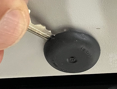
If your printer has two rubber plugs below the control pad, remove both and identify which is best aligned with the screw.
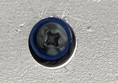
Identify whether the head of the screw in your printer has a Phillips or Allen-type head.
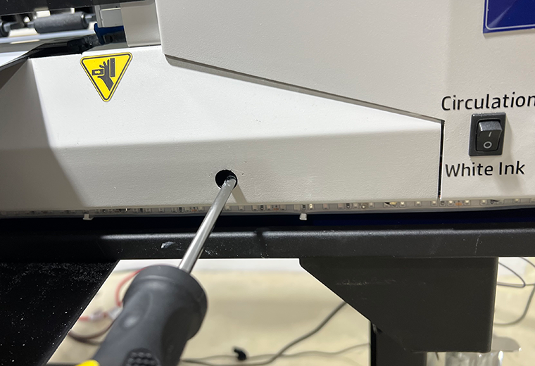
Rotate the screw counterclockwise to lower the capping station platform until it can turn no further in that direction.
Remove the right side window for a clear view of the side of the capping station platform to visually confirm the capping stations’ downward movement.
After the capping stations are fully lowered, manually push the carriage to its fully leftward position to perform the routine shutdown maintenance.
Confirm that the carriage is all the way to the left as far as it can go. If it is positioned over the platen, the heat rising from the platen heater can cause the ink in the printhead nozzles to dry out and clog them.
With the carriage at its full left position, you can now perform all of the routine shutdown maintenance steps.
Manually Putting the Carriage in its Home Position
The printhead carriage’s Home position is not its fully-right position. That would be too far right and the nozzle plates and capping stations may not be properly aligned.
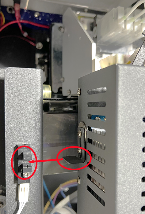
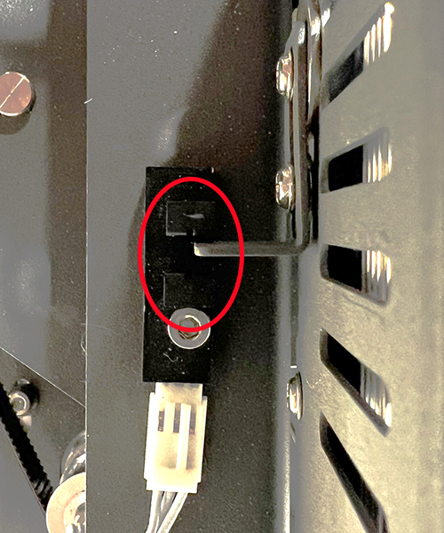
Use the metal tab on the right side of the printhead carriage and the slotted sensor on the carriage frame to find the Home position. The correct carriage position is when its tab reaches the assembly’s sensor window, at the mid-point of the slot.
Position the carriage so the end of the metal tab just reaches the center of the sensor’s gap.
Manually Wet Capping the Printheads
At this point, you should have already performed the shutdown maintenance, filled the capping stations with Super Cleaner, and moved the carriage to its Home position. If not, do that now before continuing.
If your printer and its control panel are working fine but you need to manually wet cap the printer because you can’t do it from the OmniDTF UI program on a PC, push the Enter button on the printer’s control pad to put the printhead carriage in its Home position, then turn off the printer’s power before proceeding.
Remove the black rubber plug(s) under the printer’s control pad, if you haven’t already done so. (See steps 1 & 2 in the Manually Releasing and Undocking the Printhead Carriage section above.)
Use a Philips head screwdriver or Allen wrench (depending on the screw head behind the exposed hole) to rotate the screw clockwise while looking through the opening made by removing the right side window to watch the capping station platform rise.
Continue rotating the screw until the capping station presses against the bottom of the printhead, then raise it about another 1/4″ or so to compress the capping station seals against the printhead plate.
The printer is now properly shut down and wet capped when the above steps have been completed.
If you haven’t already done so, this is a good time to empty the waste ink bottle and confirm that all of the ink clips are closed.
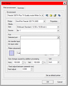
Problem: An update for Windows 11 has been found to block DirectRip from loading the list of available printers in the Print Setup window, so the R2400 device name is no longer available for selection.
Preliminary checks: There are a few things other than a Windows 11 update that may result in the printer being missing from the available Port options in the Print Setup window. Check these fundamental items before proceeding with the fix for Windows 11.
Confirm that the Freejet printer is completely turned on with the Power light on the control pad lit.
Confirm that the Maintenance tab of the R2400 driver’s Printing Preferences window can send a head clean or nozzle check to the printer.
Confirm that DirectRIP is running as Administrator. If you’re not sure, right-click on the icon for a Run as administrator option.
If the above three points check out, proceed with the fix for the Windows 11 issue.
Solution: Close DirectRIP (if it is running) and then run the “Updater” patch tool linked at the bottom of this article using the following steps:
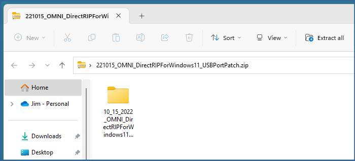
Download ‘221015_OMNI_DirectRIPForWindows11_USBPortPatch.zip‘ from the below link to the PC with DirectRIP on it.
Double-click on the downloaded .zip file to view its contents in Windows File Explorer.
Click & drag the ‘10_15_2022_OMNI_DirectRIPForWindows11_USBPortPatch‘ folder from File Explorer to the Windows Desktop.
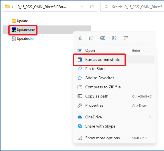
Double-click on the new folder that was copied to your Windows Desktop (‘10_15_2022_OMNI_DirectRIPForWindows11_USBPortPatch‘) to open that folder and display its contents.
Right-click on Updater.exe, then click on ‘Run as administrator‘. If Windows prompts you with the message, “Do you want to allow this app to make changes to your device?“, click the ‘Yes‘ button.
When prompted with the following message, make sure that DirectRIP is not running and then click the ‘Yes’ button.
The DirectRIP folder will be displayed in a new window. Just click the ‘OK‘ button to continue.
That’s it! You can now load DirectRIP and the printer will now be listed in the Print Setup as an available Port to select.
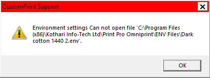
While the below-pictured DirectRIP error message may seem alarming, it is easy to resolve using the steps detailed below.
Your exact file path and filename in the message may differ, but the same solution applies.
Why is this happening?
This error will occur if a DirectRIP installation has missing or corrupt files that are needed when an Environment is selected.
How to resolve the issue
There is a video following these instructions which demonstrates steps 3-6.
Close the DirectRIP program if it is running
Download the ‘RIP Files.zip’ archive file from the link at the bottom of this article to your Windows Desktop
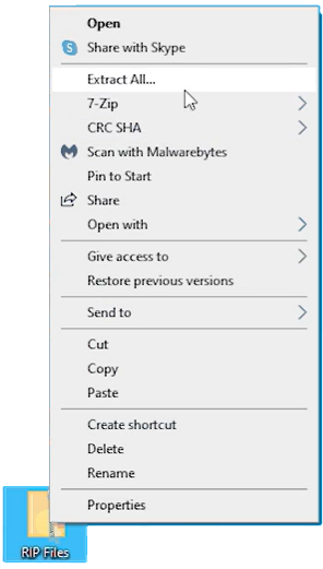
Right-click on the downloaded ‘RIP Files.zip’ and select ‘Extract All…’
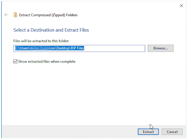
Click the ‘Show extracted files when complete’ checkbox, then click the ‘Extract’ button
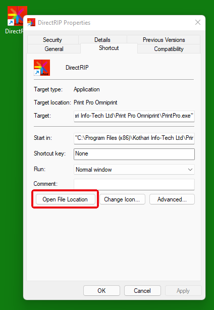
Right-click on the DirectRIP shortcut, select ‘Properties’, then click on ‘Open File Location’ from the ‘Shortcut’ tab in the ‘DirectRIP Properties’ window
This will open the DirectRIP application folder in another File Explorer window
Copy the three folders from the newly created ‘RIP Files’ folder to the DirectRIP application folder
Allow Windows to replace any & all existing folders and files when prompted
Solution video clip
Expand the below video to full screen for the best viewing experience.
Next time you start DirectRIP, the Environments will work as expected without the error message.
A grinding sound coming from your printer means that routine maintenance needs to be performed. We’ll cover some details about why this can happen and what type of maintenance, but first let’s run through a brief explanation of what causes the grinding sound.
What is Making that Sound?
A rubber drive belt connects the carriage drive motor to the print head carriage. This belt is firmly attached to the print head carriage, so if the motor is turning but the carriage can’t move, then the drive belt will slip on the motor’s cog. The grinding is the sound of the drive belt slipping across the motor’s cog.
Read on to see two reasons why the carriage may not move properly when the motor is engaged and how to resolve them both.
Ink Build-Up In the Pump
Ink build-up in the pump is the most common cause of grinding, due to the carriage being stuck in its docked position. Fortunately, it is easy to prevent by diligently cleaning the capping station and wiper blade areas of the pump, which is part of the daily maintenance routine — that is, the maintenance that should always be performed at the conclusion of any printing day.
How is it that ink in the pump can keep the carriage from moving?
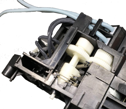
Before directly answering that question, it’s helpful to understand that the pump does more than the obvious work of pumping. It’s set of gears and the related electronics also control rotation of the wiper blade, raising and lowering the capping station, as well as raising and lowering the carriage lock arm.
Bottom view of the pump mechanism, exposing gears for wiper blade & carriage lock arm movement
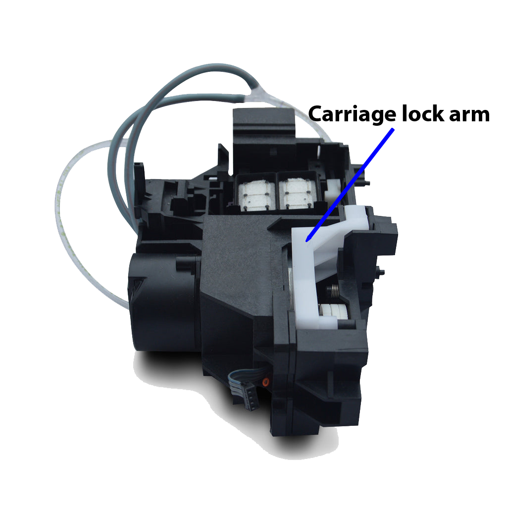
The carriage lock arm is in the left-rear section of the pump (when viewed from the front of the gantry.) When raised, the lock arm protrudes into a slot on the carriage assembly, locking it into position and preventing movement of the carriage until the lock arm is lowered.
Top of pump, viewed from the rear
Now, with the understanding that the pump includes a set of gears and other moving parts (the wiper blade, capping station, and carriage lock arm), we can understand that it’s not the ink that flows through the pump when priming or running head cleans that can lead to the grinding sound. Instead, it’s ink that can gradually drain down from the wiper blade area and down into the gears inside the pump.
This is one reason why the daily maintenance of the wiper blade and capping station areas are so important — to prevent the long-term drainage of ink down into the gears that control the movement of the carriage lock arm.
If you hear the grinding sound, do a thorough cleaning of the wiper blade and capping station area (see the below video for details), then reset the printer from its main power switch in the rear. If that doesn’t resolve the problem, proceed with cleaning the encoder strip.
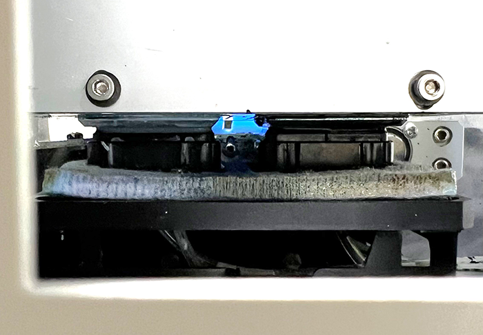
A Dirty or Damaged Encoder Strip
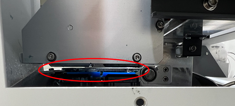
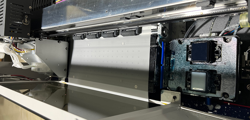
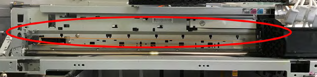
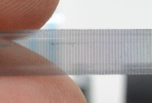
The encoder strip provides a sensor on the printer’s carriage with necessary guideposts for keeping track of its horizontal position. These guideposts are in the form of thousands of tiny vertical lines running along the full width of the carriage, from left to right.
The encoder strip appears to be grey from a distance
A closer view of the encoder strip reveals that it’s transparent plastic with thousands of vertical lines
If the encoder strip becomes dirty then the printer may not be able to gauge its position accurately, and this can also result in the carriage belt grinding due to continuing to drive the carriage to the right after it has already reached its home position.
Cleaning the encoder strip is part of the routine weekly maintenance for Freejet 330-series printers, so your User Manual has detailed instructions on the procedure, beginning on page 31. (See links to the Freejet 330-series manuals below.) After thoroughly cleaning the encoder strip, turn the printer’s main power off for a few seconds from the rear switch, then back on.
If the grinding occurs again very shortly after performing the pump and encoder strip maintenance tasks referenced above, please contact Technical Support for further help.
OmniPrint recommends resetting the waste ink pad counter of FreeJet 330-series printers on a monthly basis. Doing so will prevent an error condition that is described at the bottom of this article from occuring.
Resetting the Waste Ink Pad Counter
See how to reset the waste ink pad counter in the below video or the following step-by-step instructions.
The Adjustment Program should be used only as directed below. Any other use without the direct guidance of OmniPrint staff is strongly discouraged and may cause problems that would not be covered by the warranty.
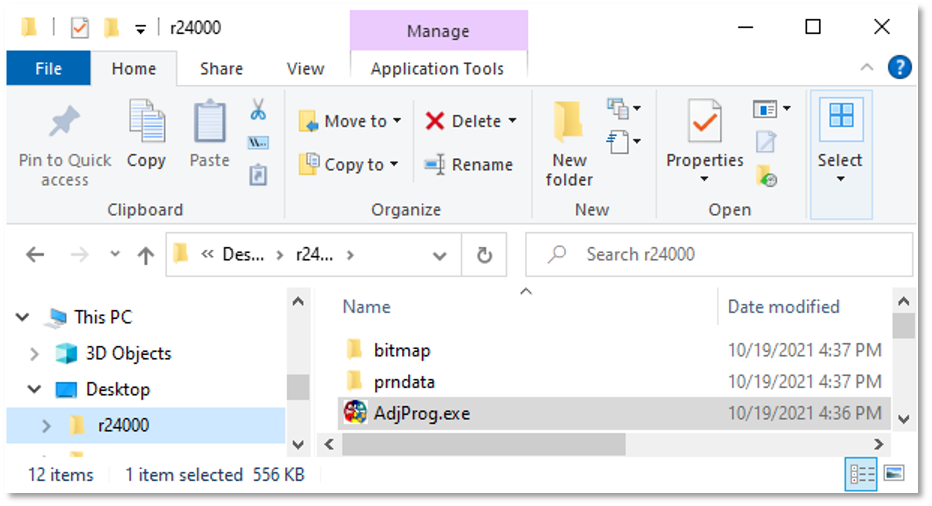
Use Windows File Explorer to navigate to where you installed the Adjustment Program, then double-click on the AdjProg program’s icon to launch the Adjustment Program.
If you don’t already have the Adjustment Program on the PC connected to your Freejet printer, you can get it and find installation instructions here.
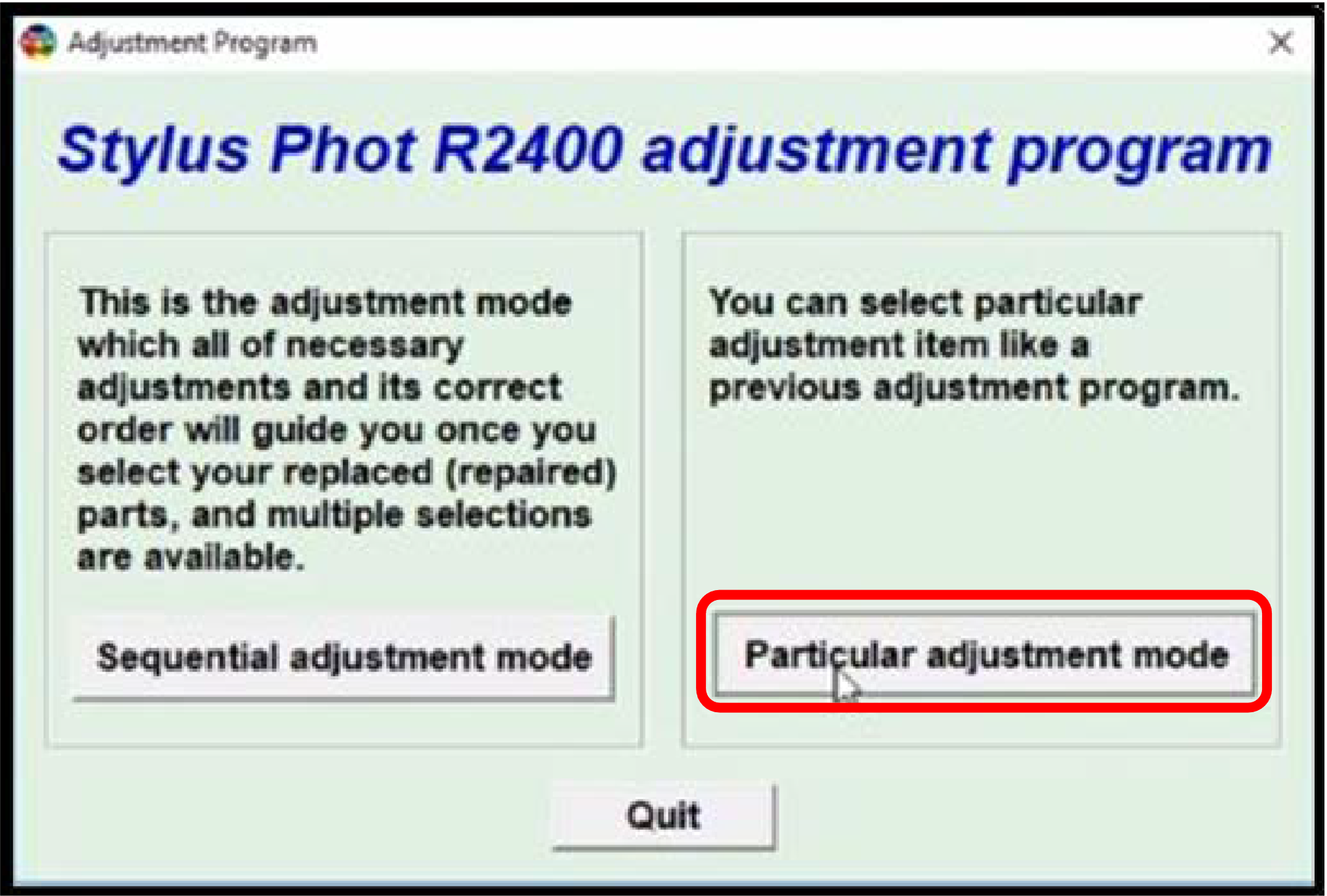
Click on the ‘Particular adjustment mode’ button.
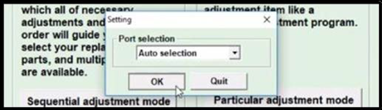
In the pop-up window, confirm that the Port selection is set to ‘Auto selection’, then click ‘OK’.
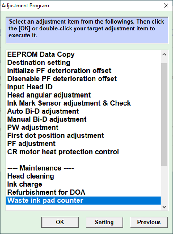
When the Adjustment Program window appears, scroll down to the ‘Maintenance’ section and select ‘Waste ink pad counter’, then click on the ‘OK’ button.
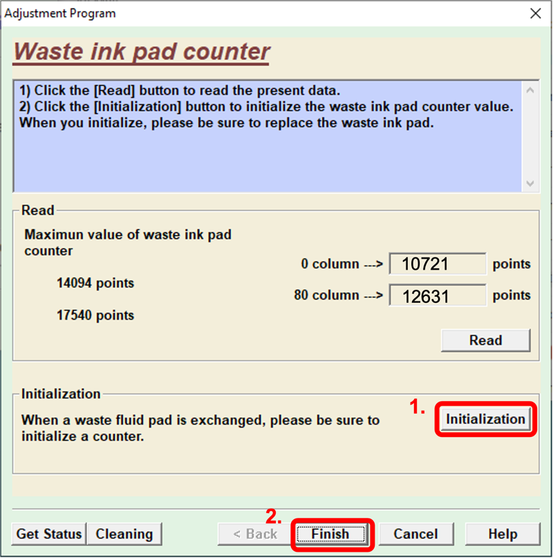
Click on the ‘Initialization’ button to reset the waste ink pad counter, then click ‘OK’ to close the informational window which pops up, then click ‘Finish’.
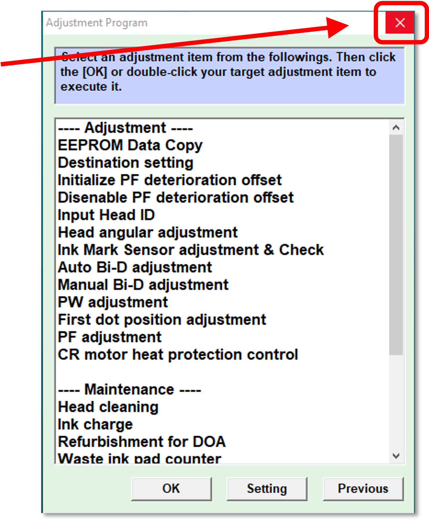
Click the ‘x’ in the upper-right corner of the Adjustment Program’s menu screen to close that window.
Click on the Adjustment Program’s ‘Quit’ button to end the program.
Turn the printer off from the rear power switch, wait 5 seconds, then turn it back on.
Congratulations! The waste ink pad counter has now been reset.
Error Condition Requiring a Waste Ink Pad Counter Reset
If a waste ink pad counter reset isn’t performed on a routine basis, the ‘Error’ and ‘Ink’ lights on the control pad will eventually begin flashing — blinking in an alternating pattern. Once this has occurred the printer will no longer accept print jobs until we acknowledge and clear the error, using the procedure detailed above. But there’s no need for that to happen.
Rather than wait for this to happen, we proactively check the waste ink tank level visually to avoid overfilling, and we use the Adjustment Program to reset the counters which trigger the error condition. By doing this as part of routine maintenance, we avoid ever having a print job interrupted by the error condition.
The absorbent waste ink pad at the bottom of the waste ink tank should be replaced once it is thoroughly saturated. This waste ink tank is the chrome, rectangular box at the left end of the printhead carriage. See our article about replacing consumable parts for details on how to replace the pad.
One of the most potentially damaging problems that can occur with your printer is a head strike or head rub. Avoiding this will extend your printhead’s life and save you the expensive of lost time & materials, and possibly expensive repairs.
What is a head strike?
A head strike is when a printhead contacts a garment, film, or platen.
Results of a head strike
If a head strike occurs, the printhead may be damaged. If the head strike is on a pretreated garment it will likely clog nozzles and may permanently damage the printhead. At the very least, a head strike will smear ink on your print so result in scrapped materials.
How to avoid head strikes
Properly positioning the platen, mounting the garment, setting the platen height appropriately (so that the print head has sufficient clearance), and keep the film properly aligned (in DTF printing) will ensure that you avoid experiencing a head strike.
What to do if you get a head strike
Immediately lower the platen (on DTG printers).
Abort the print job.
Prime all ink lines for a full pump cycle (on Freejets) or Load Ink for 15 seconds.
Monitor the waste ink bottle and interrupt priming to empty it, as needed.
Run two head cleans
Print a nozzle check
If the nozzle check is good, continue printing to keep ink flowing through the nozzles, then wet cap in Super Nozzle Cleaner overnight when finished printing.
If a good nozzle check cannot be achieved by following the above steps, contact tech support to see if permanent damage can be avoided.