Nozzle check test prints are used to determine whether or not ink flow is on track to deliver the outstanding print quality that OmniPrint products are known for. We use nozzle checks to avoid wasting consumable materials if the printer requires more preparatory steps before doing production work.
The below video demonstrates how to print a nozzle check test pattern on a Freejet 330-series printer.
Cleaning the printhead of Freejet printers is automated and can be done from the printer’s control or from its driver software. Running head cleanings is part of the production day startup process and is also useful to keep print quality high in larger production runs.
The below video demonstrates how to perform a head cleaning on Freejet 330-series printers.
White ink pigment is heavier than the pigment of the CMYK colors. Gravity will cause the white pigment to settle at the bottom of ink lines and bottles if the printer is idle for more than a day or two.
The below video demonstrates how to prime the white ink lines in a Freejet printer to flush out separated white ink and fill the white ink lines with opaque white ink to deliver a strong underbase and vivid colors in your prints.
The below video demonstrates the startup process for Freejet 330-series printers that are fully installed and already being used for production work.
This video includes a demonstration of the white ink circulation feature of the 330TX PLUS. This feature minimizes the need for priming the white ink lines for separation.
For both the 330TX and the 330TX PLUS models, it is helpful to shake the white ink bottles regularly to thoroughly mix the white pigment and to counter the development of sediment on the bottom of the white ink bottles from pigment settlement.
It’s recommended that this be done during the shutdown process, but if the printer has been idle for several days then it’s recommended to mix the white ink before starting up the printer, waiting at least 15 to 30 minutes before starting up so any bubbles introduced from shaking the ink can first dissipate.
When finished, use a clean cloth to wipe away any ink that appears to be blocking the breathing holes in the center of the bottle caps.
Transferring a finished print to a garment is simple and can be done immediately after DTF printing and curing, or up to a month later. Longer storage times may be possible if carefully stored in an air-tight container and in a climate-controlled environment.
Prepare your heat press for a DTF image transfer.
Some materials may transfer best using parameters outside of these guidelines. Use the settings that bring the best results for your materials.
Fabric Type
Temp (F)
Pressure
Transfer PressTime
Peel Delay (cold peel film)
Finish PressTime
Cotton
300◦ to 320◦
50-70 PSI Stahl’s 5-7
20 sec
60-90 sec
10-20 sec
Polyester
260◦ to 280◦
50-70 PSI Stahl’s 5-7
20 sec
60-90 sec
10-20 sec
If you experience the film coating itself transferring to polyester or poly blend fabrics (example photo), try increasing the temperature to 300 and the transfer press time to 30-45 seconds.
Cut out the image that you want to transfer to a garment from the film roll or sheet.
Place the garment to receive the image transfer onto the heat press.
An initial pre-press of the garment prior to the transfer press can be helpful to remove any wrinkles and slight moisture in higher humidity environments.
Place the DTF print on the garment, with the ink & glue side of the film directly against the fabric, positioned exactly where you want it transferred.
Verify that the collar, shoulders, and any seams are draped off the side of the heat press to ensure proper pressure at the transfer location
Place a silicone sheet or kraft paper on top of the film.
Press the transfer onto the fabric using the above table for temperature, pressure, and duration.
Remove the garment from the heat press, and lay it on a clean, flat, hard surface.
When using cold peel film, delay this step for a minute or so, until the inked area of the garment has cooled down to room temperature. Carefully peel the film away from the garment at a moderate rate.
Place the shirt back on the heat press with a sheet of parchment or Kraft Paper or a white silicone sheet between the shirt and the top of the heat press, then perform a final “finish” press for the duration shown above at the same temperature and pressure as the transfer. This further cures the surface of the print and creates a smoother transition between ink & fabric.
This video demonstrates and explains the importance of cleaning the print head brackets, undercarriage, capping station seals, and wiper blade, along with how to properly flush out the capping station sponges and wet cap the printer.
In addition to the critical preventative maintenance steps detailed in the above video, it’s also recommended to shake the white ink bottles after shutting down the printer.
This both helps to keep the white ink well-mixed and also counters development of sediment from collecting in the bottom of the white ink bottles. Press a clean cloth or finger against the ink bottles’ breather hole to avoid spillage and shake the bottle aggressively for 15-30 seconds to thoroughly mix the ink.
When finished, use a clean cloth to wipe away any ink that appears to be blocking the breathing holes in the center of the bottle caps.
This video demonstrates and explains the initial ink line filling, priming, head cleans, and nozzle check test of a new printer.
Note that although the printer in this video has its ink lines full of ink at the beginning of the initial startup process, the directions are provided for a first-time startup of a new printer with ink not yet in the ink lines.
DTF printing comes with its own unique set of advantages so many DTG printer operations are running some of their print jobs using the DTF technique!
Freejet printers are fully capable of printing vibrant, durable, and profitable transfers. Best of all, expanding your Freejet operation to include film transfer printing is easy, requiring just a few modifications to your software and workflow!
This guide will take you through the process of importing the latest DTF Environments for the Freejet 330TX or 330TX Plus into DirectRIP, so you can try out this exciting kind of garment printing yourself!
Loading the DTF environments into DirectRIP
Download links for the Freejet 330TX and 330TX Plus DTF Environments (.kie files) are listed at the bottom of this article.
Make sure that the file that you download matches your printer model as the different inks in the 330TX and the 330TX Plus require different Environments. Using the incorrect environment can result in ink bleeding or poor adhesion.
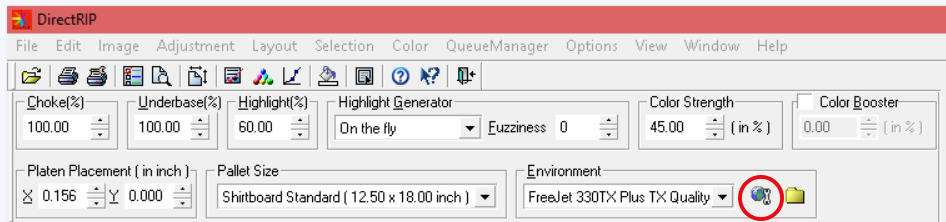
In DirectRIP, next to your “Environment” drop-down box, there is an icon that looks like a globe with a wrench for ‘Manage Environment’.
Click this ‘Manage Environment’ icon.
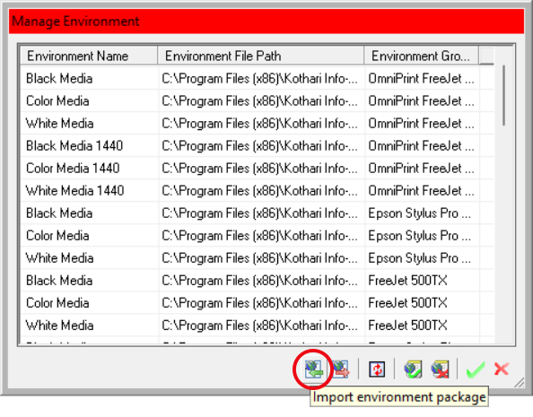
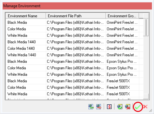
The ‘Manage Environment’ window will open. Click the leftmost icon at the bottom of this window to open the ‘Import Environment Package’ window.
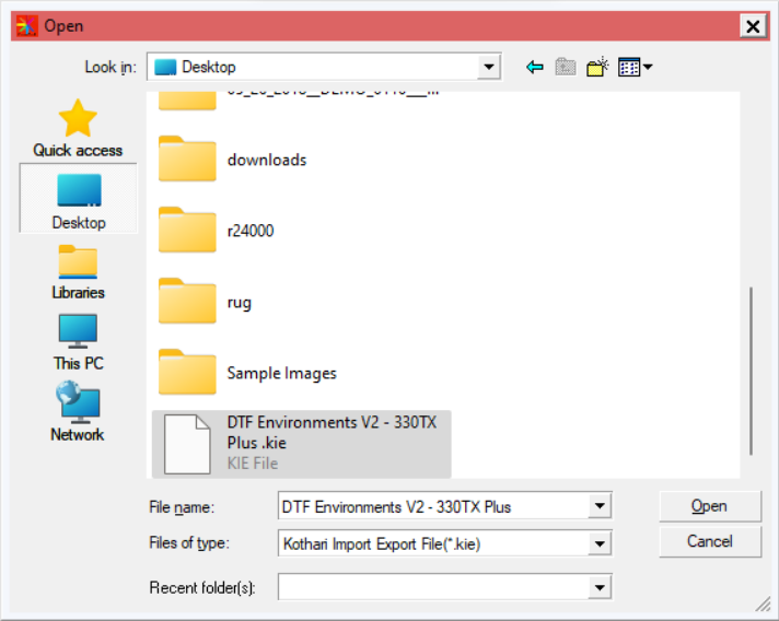
In the window that appears, navigate to where you saved the downloaded .kie file, select it, and click the ‘Open’ button.
The below screenshot examples are for a previous version of Environments for the Freejet 330TX Plus. There will be differences in file & Environment names for later versions, but the process is the same.
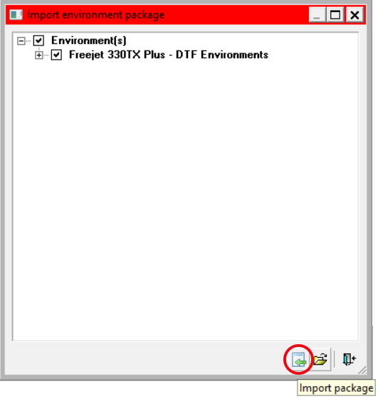
You should arrive at this window:
Click the ‘Import Package’ icon. This will import the new environments and the ‘Import environment package’ window will automatically close.
Next, click the green checkmark on the ‘Manage Environment’ window to save the update and close the menu.
That’s it! The environments are now fully installed! You can now use them to print transfers!
It’s important to have a basic understanding of how the ink delivery system works and the parts that are involved. Knowledge is power, and understanding the basics of how ink gets from the bottles to the print head empowers us to use deductive reasoning to quickly troubleshoot and resolve most ink flow issues.
Here’s a full list of the components of the ink delivery system:
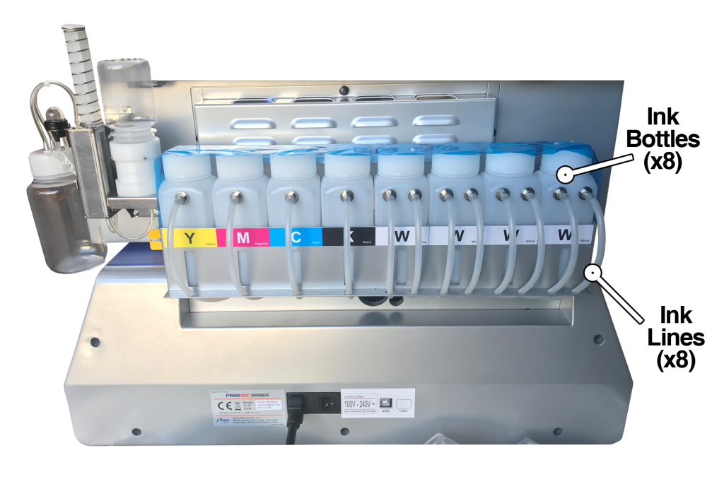
Ink bottles (8)
Ink lines (8)
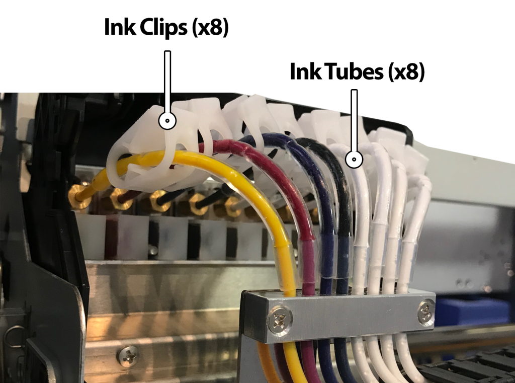
Ink tubes (8)
Ink clips (8)
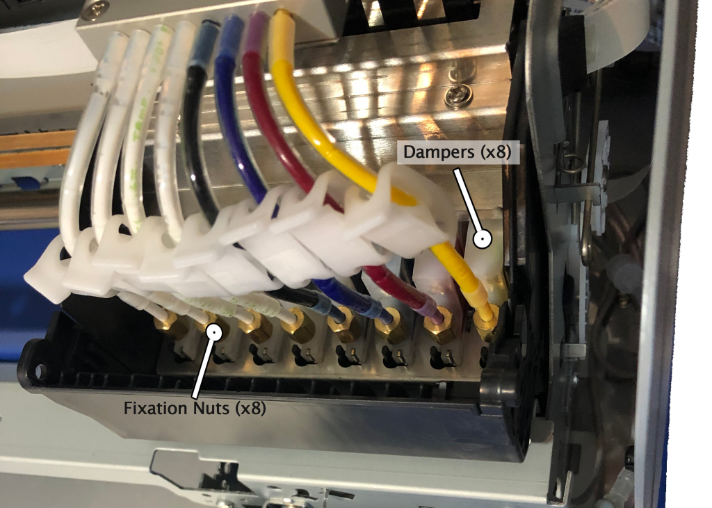
Dampers (8)
Damper fixation nut (8)
O-rings (8)
Print head
Pump with capping station
Since we have eight ink channels (cyan, magenta, yellow, black, and four whites), there are eight of each part in the ink path until we get to the print head.
Let’s first define the purpose of each component, and then we’ll briefly go over how they all work together to get ink from the bottles and onto the garments when we print.
Component Functions
Ink bottles: The ink bottles provide a reservoir of ink for each channel. These are the beginning of the ink path for each of the eight ink channels. Each bottle has a metal fitting, through which an ink line will pass as it moves out of the bottle.
On the Freejet 330TX Plus model, there will be a second fitting on each white ink bottle. This is where white ink returns to the bottle when the circulation pumps are running. However, this white ink circulation circuit isn’t functionally part of the ink delivery system so won’t be detailed further here.
Ink lines: The translucent, plastic ink lines provide the majority (roughly 90%) of the path between the ink bottles and the print head. In combination, they’re an 8-lane ink expressway with no stops and no lane changes allowed.
One end of each ink line passes through a fitting on its ink bottle and extends down to about 1/4″ to 1/2″ from the bottom of the bottle. The other end of each ink line terminates inside the gantry, where it connects to an ink tube.
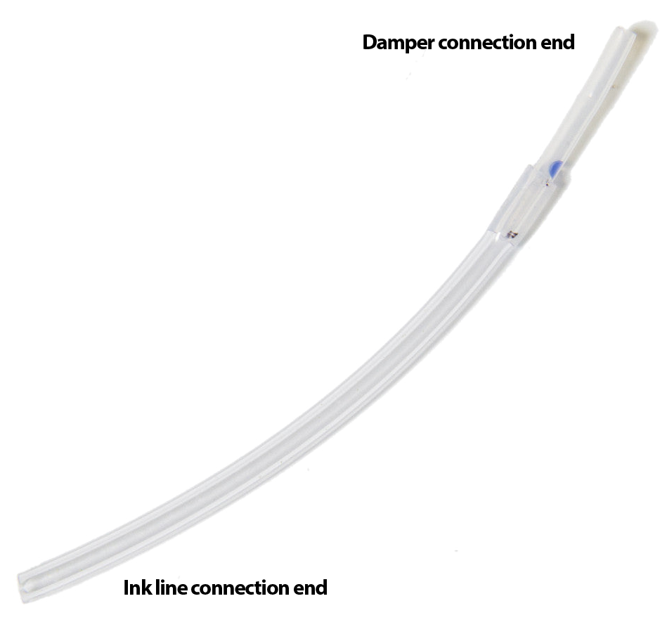
Ink tubes: The short (about 3″), softer plastic ink tubes are the “last mile” of the ink path, providing a flexible interconnection between the ink bottles and the dampers. If the ink lines are an ink expressway then the ink tubes are the off-ramp where the ink has almost reached its destination.
The Ink Tube connects the ink line to the damper.
The larger end of the ink tube tightly slips around the ink line, while the small end is attached to the damper with an o-ring and copper-colored nut.
Ink clips: The purpose of the ink clips is to crimp the ink tubes and shut off ink flow when desired (such as when the printer is idle.)
Dampers: Dampers provide the final “Quality Assurance” for ink with their mesh filter, which serves to trap bubbles and any dried ink or foreign material that doesn’t belong in the ink supply. (Better to replace a clogged damper than to have to replace a clogged print head.)
Damper fixation nuts & O-rings: These two parts complete the air-tight, mechanical connection between the ink tube and the damper. The o-ring goes around the smaller end of the ink tube and presses against the inside of the fixation nut to ensure an air-tight connection when the nut is attached to the damper.
The dampers and their associated o-rings and fixation nuts are the last components in the printing ink path before the print head.
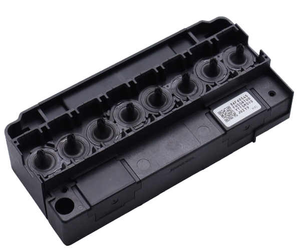
Print head: The print head is where it all comes together — literally. All eight of the ink channels feed into the eight posts on top of the print head, to which the dampers directly connect.
Print head top, with damper posts.
The purpose of the print head is, of course, to deliver the ink to the garment that we’re printing onto through the over 1,400 tiny nozzles of the print head plate, on the bottom of the print head.
All of the components listed above except the print head itself are completely passive while the printing. That is, they are simply a conduit for the ink to travel through.
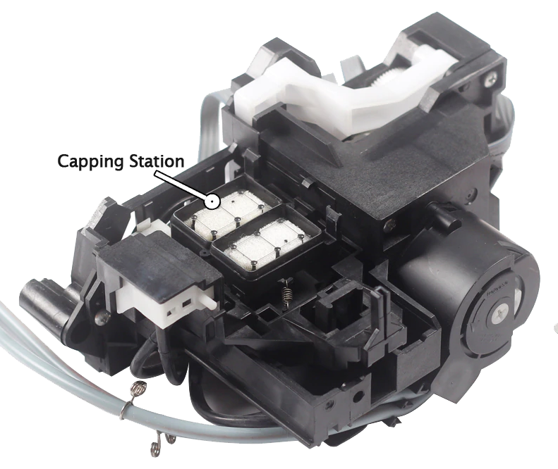
Pump with capping station: Ink doesn’t actually flow through the pump when we’re printing, but it’s included here because it is instrumental for priming and for running head cleans before or between print jobs.
The purpose of the pump, with regards to ink delivery, is to pull ink through the print head nozzles when priming and running head cleans, but not when printing.
Ink Flow Dynamics
When printing, ink is jetted out of the print head nozzles by micro-piezo electronics within the print head. This creates pulses that push drops of ink out of nozzles as the carriage moves back & forth. This happens very quickly and very precisely in order to produce high-quality prints at high resolution.
You may wonder, if it’s only the print head that actively does anything to make ink flow while printing, what causes the ink to flow into the print head while printing? Essentially, it is gravity — but more specifically, the ink delivery system is a type of siphon. As the print head expels drops of ink, the siphon effect causes more ink to be drawn into the print head from the bottles, through the ink lines, tubes, and dampers.
In order for ink to flow properly through a siphon system, every component and connection in the system must be air-tight. So while this isn’t a troubleshooting guide, if one of your ink channels starts dropping out while printing after getting a perfect nozzle check, you may want to verify the following: