Consumable parts are those parts that are expected to require replacement on a regular basis, as part of normal maintenance for optimal performance and reliable operation, not due to any manufacturing defect.
While consumable parts are expected to require replacement as part of normal system maintenance, you can maximize the service life of these components by staying on top of your routine maintenance schedule.
Parts that are exposed to both ink and air need to be cleaned after each day of usage, to prevent ink from drying and building up over time. Ink build-up on the capping station, wiper blade, or printhead undercarriage can result in nozzles clogging and potentially require replacement of the printhead. Diligent and thorough maintenance is the best way to minimize the need for consumable parts replacement.
Probably the most familiar examples of consumable parts are tires and air & oil filters on a car. The fact that they have to be replaced periodically does not point to any type of flaw — it’s normal and expected.
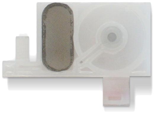
A damper for the Freejet 330-series DTG printers — a consumable part.
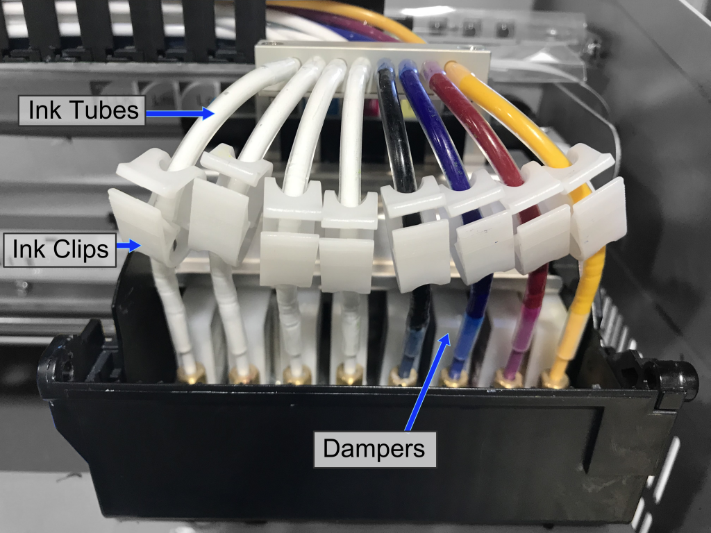
Some of our consumable parts are dampers, ink clips, ink tubes, o-rings, and pumps. Just like tires wear out, so do consumable parts on your printer. These types of consumable parts periodically need replacement due to normal wear.
Your warranty does cover any defects in parts or workmanship, and if a consumable part is deemed by OmniPrint staff to have been defective on a brand new printer it will be covered. We also provide a limited warranty on the printhead against spontaneous clogging, while other DTG manufacturers typically treat print heads as consumable parts. (Damage or clogging due to head strikes or lack of maintenance is not covered.)
The Freejet Support Kit consists of the following items:
Pump
Pump Soak Pad
Waste Ink Pad (for spit tray)
Dampers (8)
FreeJet Clips (8)
Ink Tubes (8)
O-rings (8)
…all of which are consumable parts for the Freejet. Most of these parts will need to be replaced on a regular basis — some within the first year. Having a Support Kit on-hand will minimize downtime, allowing you to usually get your printer back up in minutes, rather than waiting for the parts to be ordered and delivered. As an added benefit, the Support Kit provides $700 worth of parts for only $575 — a discount of almost 20%!
This article will discuss each part in the Support Kit, and serve as a brief How-To Guide for replacing those parts. We recommend reading this entire article before doing any disassembly. You may also wish to review the following video before replacing dampers.
Damper Replacement Video
Dampers, Ink Tubes, Clips, and O-Rings
Tools needed: small or medium needle nose pliers, #2 Phillips head screwdriver
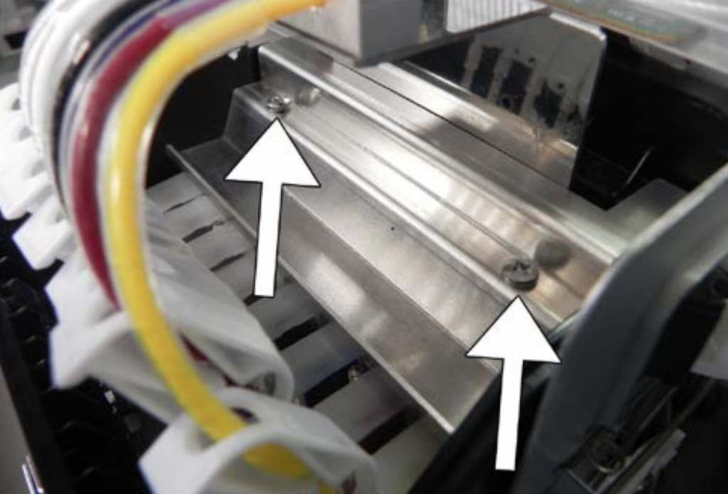
On the top of the print head, locate the staircase-shaped metal plate. This is the Damper Panel.
Two screws hold the damper panel in place.
Use your #2 Phillips head screwdriver to remove the two screws holding the damper panel in place. Slide the damper panel off, then set it and the screws carefully aside.
Damper Removal
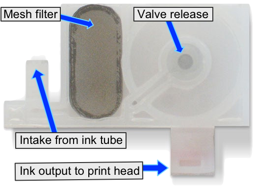
It is important to take care to avoid ink spills inside the print head carriage, so note that the dampers have a disc-shaped valve that will release ink from the bottom of the damper if the valve is squeezed from the sides of the diaphragm.
If any ink should spill inside the Print Head Carriage, clean it out immediately. If allowed to remain in the carriage, the ink can drain onto electronics and cause severe and costly damage to the machine.
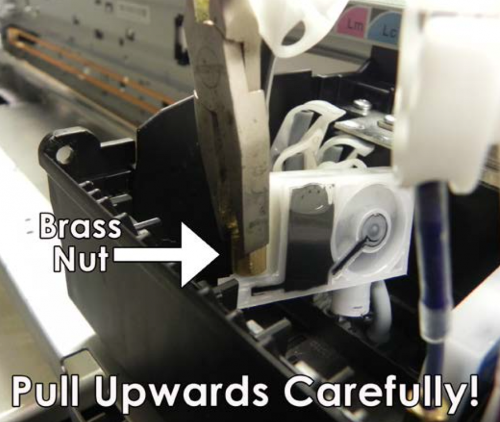
Using your needle nose pliers, grasp the brass nut at the front of each damper and gently lift straight up to pull the dampers out of their positions. It may be helpful to slightly rock the damper from front to back to release its seal on the top of the print head nozzles, but avoid rocking side to side.
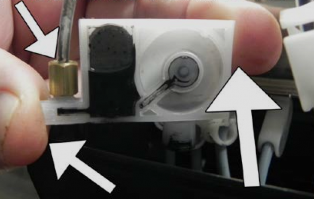
Only grasp dampers by the brass nut at the front of the damper or by the front and rear outer edge of the rigid frame (not by the wide, thin sides) to avoid accidentally puncturing the thin plastic diaphragm.
Demonstration of proper damper handling, using only the front & back of its frame or the brass nut.
Once dampers have been lifted up, allow them to hang in front of the Print Carriage, for now. Ink may drip from the dampers so it’s recommended to put a scrap shirt, shop rag, or paper towel directly under the dampers.
Unscrew the nut from each of the dampers and slide it up the ink tube a bit to expose the o-ring (to ensure that it doesn’t fall off), then pull the end of the ink tube off of the damper.
Evaluation & Replacement of Ink Tubes, Clips, and O-Rings
At this point we want to evaluate the condition of the printer’s ink tubes, clips, and o-ring. If any of those parts are showing signs of significant wear then this would be a great time to replace them.
Here’s what to look for:
Ink tubes – Replace when out of round with severe crimping which may restrict ink flow
Clips – Replace with any sign of brittleness or cracking
O-rings – Replace if no longer supple or with any sign of cracking, brittleness, or distortion of perfectly round shape
Regardless of their condition, some customers prefer to proactively replace these parts on a regular schedule, all at once, before they impact print quality to minimize future production interruptions.
If replacing only the damper, skip to that section below.
If you are replacing the ink tube, clip, or o-ring, first slide (or roll) the o-ring off of the ink tube, then slide off the brass nut. If replacing the clip, slide that off next.
If you are replacing the ink tube itself, observe where this short ink tube connects to the main ink line as an overlapping, air-tight sleeve.
It is best to push the ink tube off of the main ink line using a thumbnail or a thin, stiff tool (with no sharp edge.) You can also try rotating the ink tube while pulling it off of the main ink line, though pulling may cause the ink tube to stretch and become tighter.
Be careful, and place a drop cloth underneath the ink lines and tubes as you do this, or you’ll risk spilling in the Print Head Carriage!
If replacing more than one ink tube, complete each ink tube (plus clip and o-ring reinstallation or replacement, as needed) before moving on to the next set. Doing them one at a time minimizes the risk posed by spills.
The order of installation for this set of parts is:
Ink tube
Clip
Brass nut (with open end facing the end of the ink tube
O-ring
Damper Replacement
To attach your new damper, push the open end of the ink tube onto the ink intake port on the front of the damper, and screw the brass nut in place to secure it, making sure the o-ring is on the ink tube and inside the brass nut’s opening. Tighten the nut so it is snug, but be careful to make it only hand tight since the damper’s plastic threads can be easily stripped if overtightened.
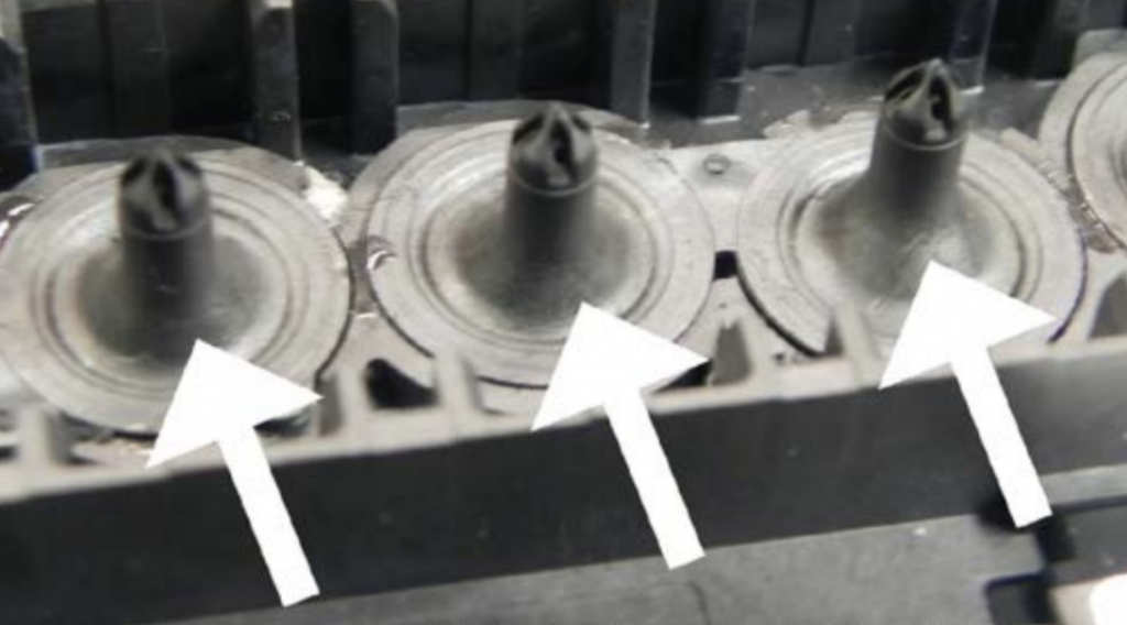
After all desired parts have been swapped, gently grasp the first damper by the brass nut, and position it so the open, circular port on the bottom of the damper is pointing straight-down over its matched nozzle post on the print head.
Print head damper posts, which dampers are mounted onto.
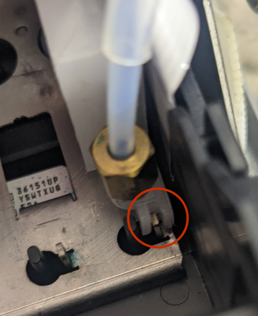
Lower the damper straight down and into position, ensuring that the plastic “U-shaped” alignment slot at the front of the damper wraps around the metal tab of the Damper Alignment Bracket.
A U-shaped slot at the front of each damper is aligned with the upright tab on the alignment plate.
Press straight down to the top of the damper, near its rear (immediately above the print head’s associated damper post) to secure it into position. You will feel a slight bit of resistance as the damper mates to the print head post, followed by firm resistance once the damper is fully seated onto the post.
Repeat for any other dampers, ink tubes, o-rings, and/or clips to be replaced.
When complete, with all 8 dampers evenly spaced and at equal height, replace the damper panel and screw it back into place.
Waste Ink Pad
The Waste Ink Pad is located inside the Waste Ink Spit Tray, inside the carriage assembly, at the far left end — opposite the print head carriage’s home position over the pump.
The Waste Ink Tank (or “Spit Tray”) contains the Waste Ink Pad
If your waste ink pad is completely submerged in ink, use a syringe to suction out the excess ink. Once the excess ink is removed, use a pair of needle nose pliers to pull out the soak pad and insert a new soak pad in its place.
Cleaning out the waste ink reservoir and replacing the soak pads
Pump and Pump Soak Pad
The Pump has a more involved replacement procedure which should only be done with the live assistance of an OmniPrint Technician, at least while the printer is under warranty. Also, replacing the pump sometimes requires access to a circuit board that can be damaged if mishandled.
Please contact our Technical Support team to request assistance if you believe the pump needs to be replaced, to avoid potentially damaging your printer and voiding its warranty.
During the pump replacement process, we also replace the Pump Soak Pad, which is placed underneath the pump.
One of the most potentially damaging problems that can occur with your printer is a head strike or head rub. Avoiding this will extend your printhead’s life and save you the expensive of lost time & materials, and possibly expensive repairs.
What is a head strike?
A head strike is when a printhead contacts a garment, film, or platen.
Results of a head strike
If a head strike occurs, the printhead may be damaged. If the head strike is on a pretreated garment it will likely clog nozzles and may permanently damage the printhead. At the very least, a head strike will smear ink on your print so result in scrapped materials.
How to avoid head strikes
Properly positioning the platen, mounting the garment, setting the platen height appropriately (so that the print head has sufficient clearance), and keep the film properly aligned (in DTF printing) will ensure that you avoid experiencing a head strike.
What to do if you get a head strike
Immediately lower the platen (on DTG printers).
Abort the print job.
Prime all ink lines for a full pump cycle (on Freejets) or Load Ink for 15 seconds.
Monitor the waste ink bottle and interrupt priming to empty it, as needed.
Run two head cleans
Print a nozzle check
If the nozzle check is good, continue printing to keep ink flowing through the nozzles, then wet cap in Super Nozzle Cleaner overnight when finished printing.
If a good nozzle check cannot be achieved by following the above steps, contact tech support to see if permanent damage can be avoided.