Why customize Environments?
As you develop experience printing a wide variety of images, you will eventually come across designs that require modifying the default parameters provided by the built-in Print Pro Environments.
Some of the easily adjustable parameters that get set to specific default values based on your Environment selection include:
- Underbase
- Highlight*
- Fuzziness*
- Color Strength
- Color Booster
These and other settings can be quickly adjusted on the fly from the Print Pro toolbar after loading your selected Environment (with its presets), and that’s the best way to make a fast, one-off adjustment.
We’ll show you how to create and save a modified Environment, customized to your parameter preferences, which can improve your workflow & efficiency if you frequently use designs that look best with modified settings.
Environment Groups
Before we create a custom Environment, it will be helpful to understand how Print Pro’s Environment Groups feature helps us keep Environments organized and easy to locate.
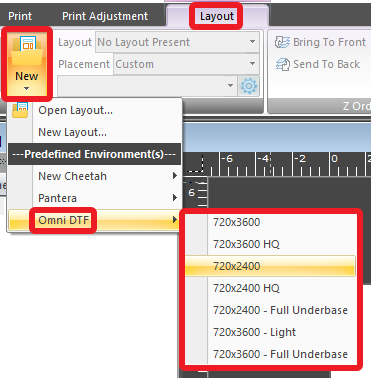
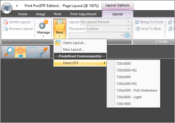
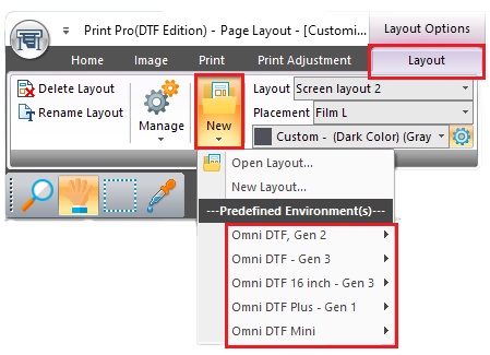
Environment Groups are like folders used to organize a set of Environments under a common category or theme. Whenever you click on the New button on Print Pro’s Layout toolbar, the product name that appears below the ‘Open Layout…’ and ‘New Layout…’ options is an Environment Group name. For example, “Omni DTF – Gen 3” and “Omni DTF Mini” are examples of Environment Groups found in Print Pro for those respective models.
Creating an Environment Group
We recommend creating new Environment Groups to organize any custom Environments you create. You may want Group names based on a client name or a particular design type — whatever makes sense to you when you’re later looking for a particular customized Environment (or set of custom Environments) is fine.
Here’s how to create an Environment Group.
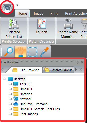
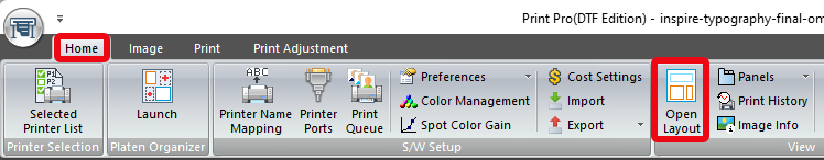
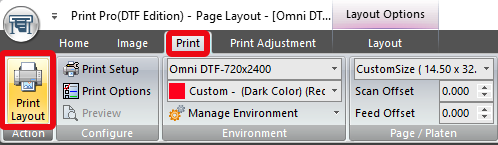
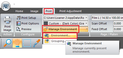
- Click on the Manage Environment button on the Print toolbar.
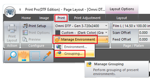
The Manage Environment dropdown options of ‘Environment…’ and ‘Grouping…’ appears. - Click on the ‘Grouping…‘ option.
The Manage Environment Group window appears.
- Click on the Add Environment group icon, as shown below.
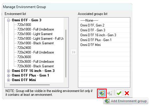
A new Group will appear at the bottom of the Environment list with an initial name of “Group 1“.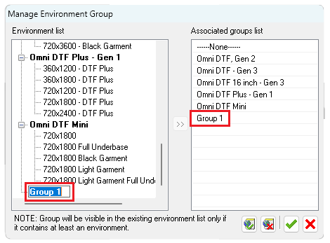
- Click on the ‘Group 1‘ new group name, type whatever name you want to call the group, then press the Enter key. For this example, we use the name ‘Custom‘.
The new Group name appears at the bottom of both lists — Environment list and Associated groups list.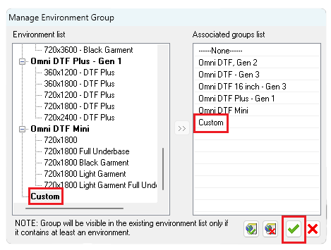
- Click the green checkmark near the bottom right corner of the Manage Environment Group window to save the new Group and close the window.
Saving a New Environment
Whenever we change options (e.g. Underbase %, Color Strength %, etc.) on the Print Adjustment toolbar, we temporarily replace the values from the selected Environment’s default settings.
Here’s how to save a set of modified values to a new Environment.
- Select an Environment to be used as the basis for a customized version. Pick the Environment with same resolution and, if applicable, shirt color so you’ll only need to make changes from the Print Adjustment toolbar.
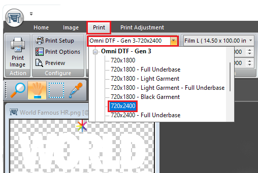
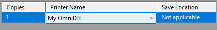
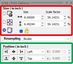
For this example, we use the Omni DTF – Gen 3 Environment Group’s 720×2400 Environment. Its presets appear on the Print Adjustment toolbar as shown below.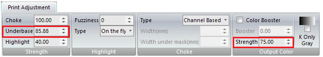
- Use the Print Adjustment toolbar to adjust the Underbase, Color Strength, or Color Booster values as desired. For this example, we will change the Underbase from 85.88% to 90% and the Color Strength from 75% to 80%.
We’ve so far created an Environment Group and made some changes to a set of default Environment parameters to create some context for what comes next.
The following steps will result in these parameter changes being saved to a new Environment which we’ll later be able to recall from the DirectRIP toolbar’s Environment dropdown.
Use the Print Adjustment toolbar to adjust the Underbase, Color Strength, or Color Booster values as desired. For this example, we will change the Underbase from 85.88% to 90% and the Color Strength from 75% to 80%.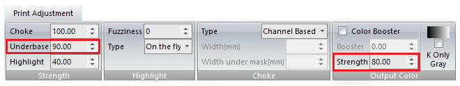
We’ve so far created an Environment Group and made some changes to a set of default Environment parameters to create some context for what comes next.
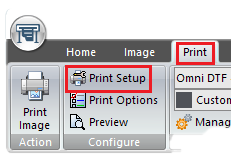
The following steps will result in these parameter changes being saved to a new Environment which we’ll later be able to recall from the DirectRIP toolbar’s Environment dropdown. - Click the Print Setup icon near the left end of the Print toolbar.
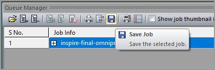
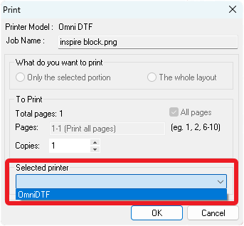
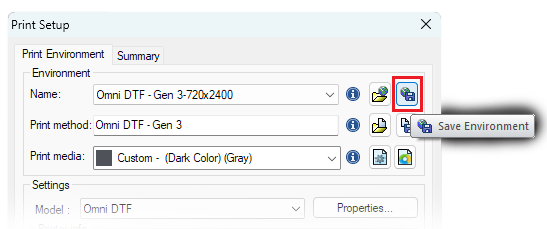
The Print Setup window appears. - Click the Save Environment button (see below), the last icon to the right of the Print Setup window’s Environment Name dropdown list.
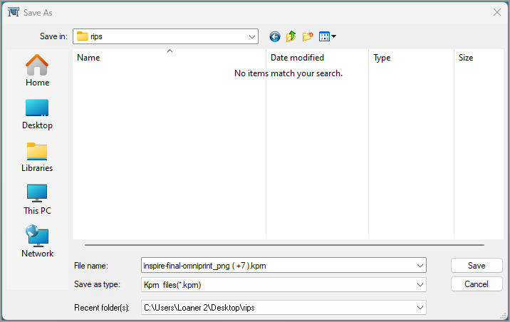
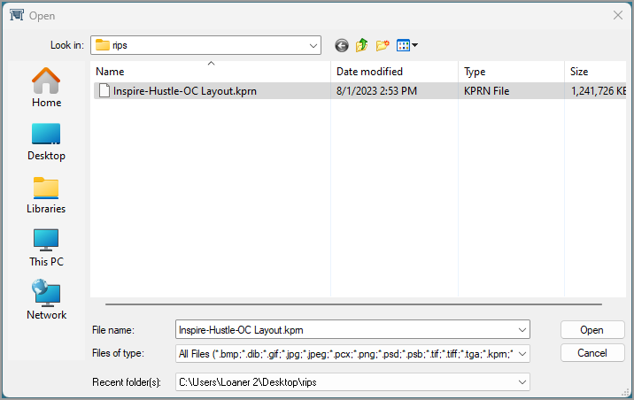
A Save As dialog window appears with the default name being that of the originally selected baseline (unmodified) Environmet in the File name text box.
- Replace the default name with a name of your choice for the new Environment in the File name text box, then click the Save button.
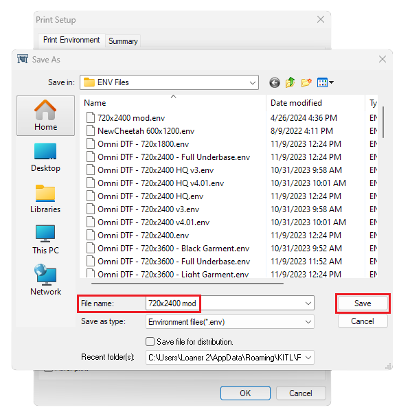
We’re using “720×2400 mod” in our example. - When the Save As dialog box closes, click the Print Setup window’s ‘OK’ button to close that window, too.
- Click the Manage Environment option on the Print toolbar, then select ‘Environment…‘.
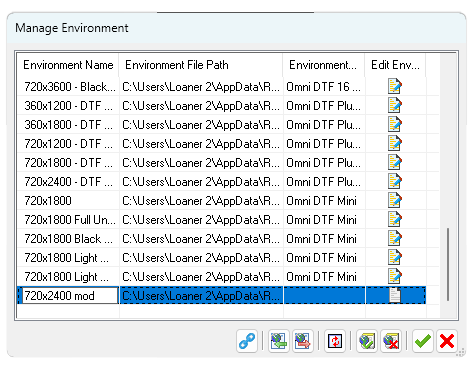
The Manage Environment window appears.
Scroll to the bottom of the Manage Environment window’s list where you will find an entry with no Environment Name and no Environment Group. This is the Environment that you created. - Click on the empty Environment Name field and type in a name for the new Environment.
The name you create here will appear when you use the toolbar’s Environment dropdown list in the future, so name your new Environment in a way that will be meaningful to you next time you want to use the same set of parameters. We’re using “720×2400 mod” again for our example. You may want to use something specific to why you’re creating a custom Environment. - Click on the empty Environment Group field, then click on the dropdown box and select the new group name you previously created.
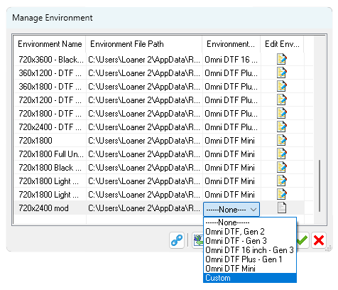
- Click the green checkmark to save your selections.
You’re finished with the process and your new Group & Environment are now available from the Layout toolbar’s New dropdown list, under the heading of your new Environment Group.