OmniPrint recommends cleaning the encoder strip and cleaning & lubricating the carriage rail on a bi-weekly schedule (every two weeks). As both procedures involve moving the carriage to the left, it makes sense to do them both at the same time.
Aside from the bi-weekly schedule, it’s advisable to also perform both tasks if you ever note inconsistent horizontal registration in your prints.
Watch the below video or read the following detailed instructions and stay on top of these two easy maintenance tasks to keep your Omni DTF Mini reliably printing at maximum quality.
Video Demonstration
The Encoder Strip
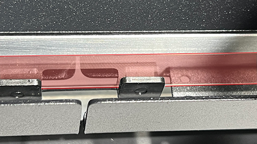
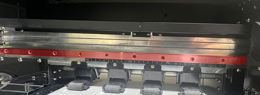
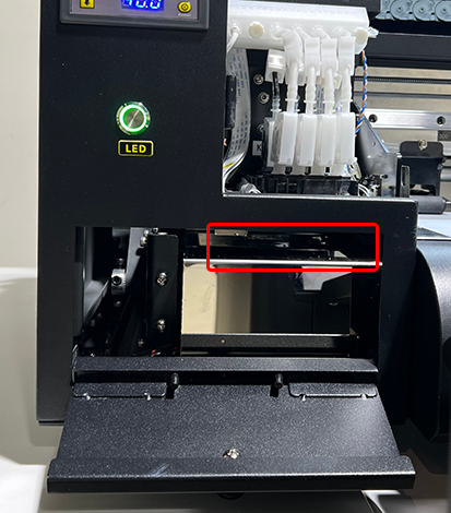
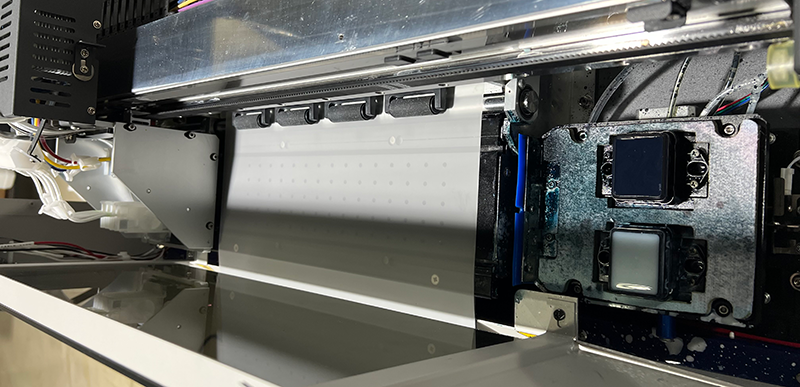
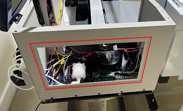
The printer’s encoder strip is a long, narrow, semitransparent plastic tape which spans the full width of the printhead carriage’s travel path. It’s covered with tiny vertical lines which are seen and counted as the carriage moves back and forth. The printer knows the exact location of the carriage at any moment based on its count of the encoder strip’s vertical lines as an offset from the carriage’s “home” position.
Omni DTF Mini encoder strip, shown with red outline & tint
The Omni DTF Mini encoder strip is positioned behind a two-piece (left & right) protective shield which helps to prevent most vaporized ink and other particles in the environment from getting onto the encoder strip, but this won’t prevent it from needing to be cleaned on a regular basis.
Using any cleaning solution other than 70% isopropyl alcohol may remove or lighten the indexing marks on the encoder strip, requiring that it be replaced in order to operate the printer.
Cleaning the encoder strip
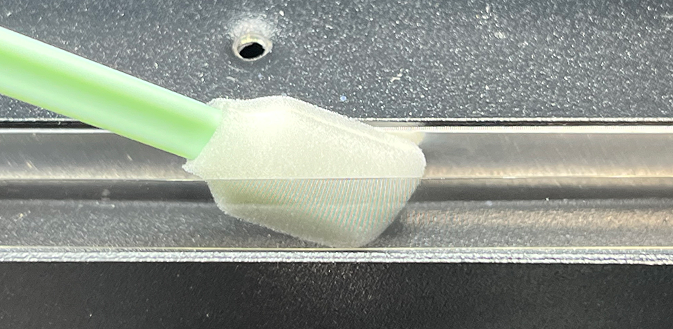
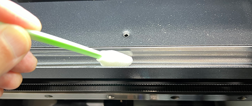
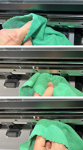
Wet a microfiber cloth or foam swab with 70% isopropyl alcohol and gently wipe both sides of the exposed section of encoder strip to the left of the carriage.
Cleaning the back side of the encoder strip.Cleaning the front side of the encoder strip.
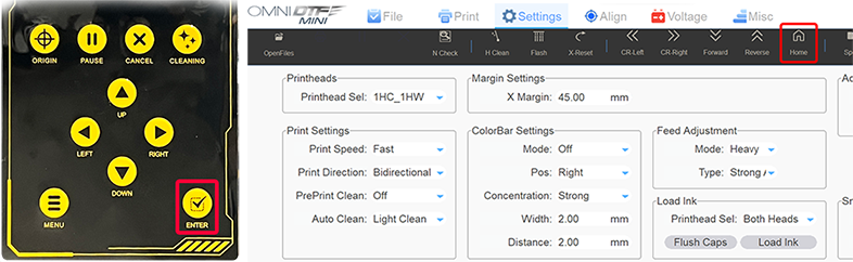
Move the carriage to its full-left position to expose the part of the encoder strip that the carriage was previously covering. Clean that additional section of the strip, then home the carriage using the printer’s Enter button or the Omni DTF Mini UI software’s Home button.
The Carriage Rail
The printhead carriage rides along a rectangular rail, gripping the grooves at the top & bottom of the rail. It’s important to keep the rail clean and lubricated to prevent excessive drag on the carriage motor and to maintain smooth operation and optimal horizontal registration.
No chemicals should be used to clean the carriage rail, and no lubricant except the blue “FreeJet” grease referenced above.
To clean the carriage bar, simply wipe down the exposed top, front, and bottom surfaces with a clean, dry cloth.
Cleaning the top, bottom, and front fact of the carriage rail (track)
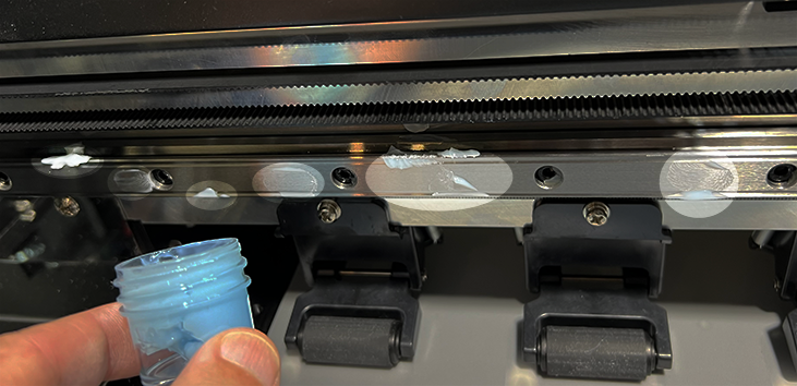
To lubricate the carriage bar, put a few dabs of blue grease across the same surfaces that were wiped down when cleaning the rail.
Omni DTF Mini carriage rail (track) with blue grease applied for lubrication.
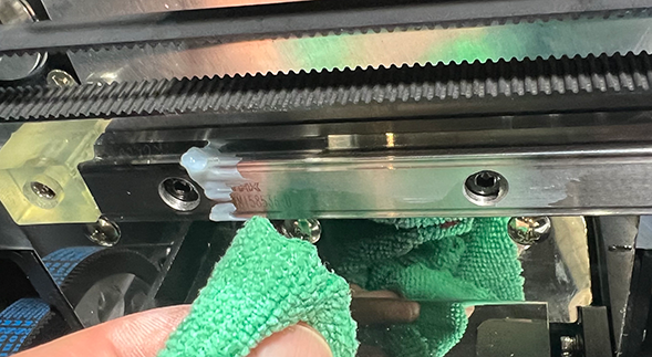
Move the carriage to its full-left position to expose the part of the carriage rail that it was previously covering. Clean and lubricate that additional section of rail, then use the carriage movement controls to run the carriage back & forth across its full range of travel to distribute the grease across the rail.
Finally, wipe off any excess grease that may build up at either end of the rail.
Removing excess grease from the carriage rail.
Home the carriage using the printer’s Enter button or the Omni DTF Mini UI software’s Home button.
As always, be sure to wet cap the printer if you won’t be using it.
The most critical maintenance task is properly shutting down your Omni DTF Mini at the end of a production day.
This shutdown maintenance supports producing high-quality prints and maximizing economical operation. That’s because everything we do during the shutdown routine is focused on protecting and prolonging the service life of the printheads.
The printer can safely be left idle for up to 3 weeks once it has been properly shut down and wet-capped. If the printer will be idle for a longer period, it’s advisable to run full startup & shutdown processes (including getting good nozzle checks) every 2-3 weeks to prevent clogging.
Follow the steps demonstrated in the below video or described in the following text each time you shut down the Omni DTF Mini to maximize the service life of your printer’s consumable parts.
Video Demonstration
Undercarriage Detail
Shutdown Summary
Turn the oven off.
Run a head cleaning.
Close the ink clips after the head cleaning is completed.
Move the carriage to its full-left position.
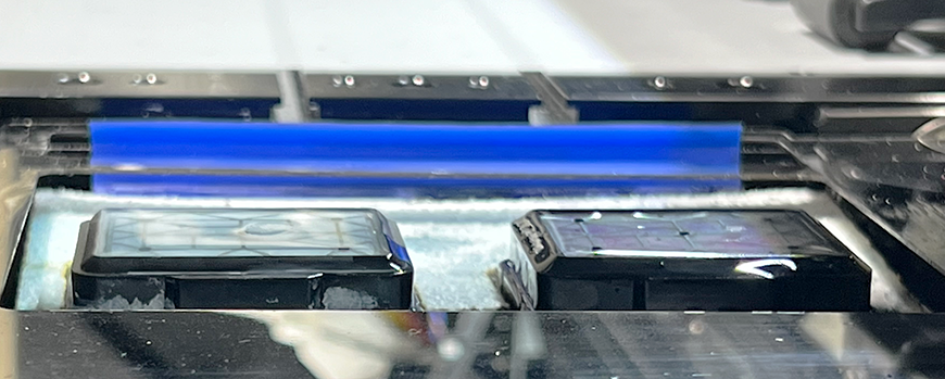
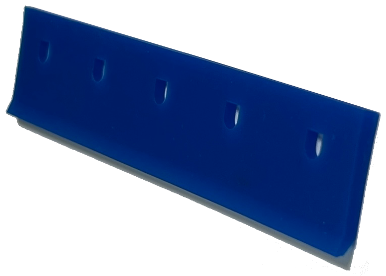
Clean the wiper blade.
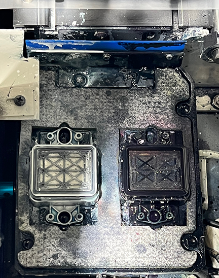
Clean the capping station seals.
Flush out the capping stations.
Clean the undercarriage around the printheads.
Wet cap the printer.
Turn the printer off.
Daily Shutdown Illustrated Details
Turn the oven off.
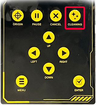
Run a head cleaning.
Close the ink clips after the head cleaning is completed.
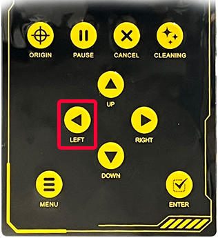
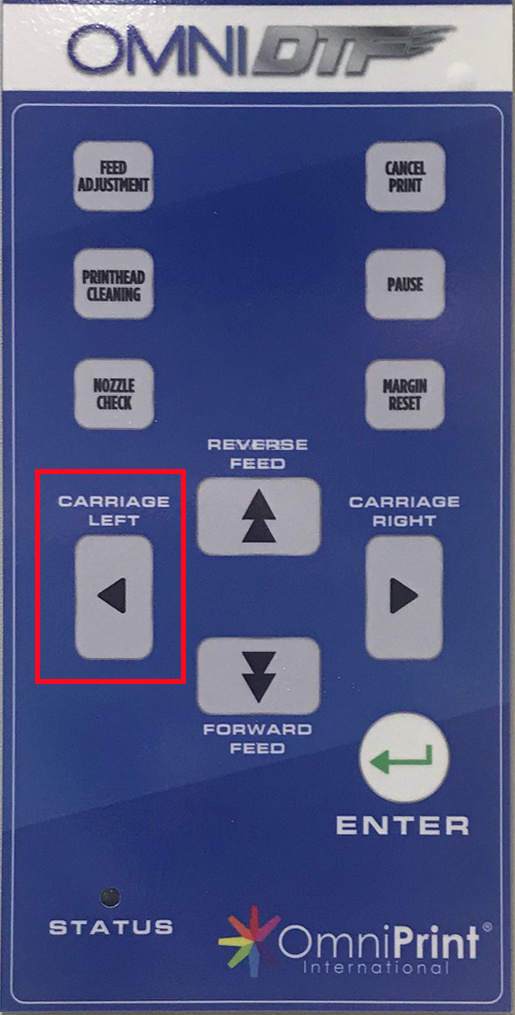
Use the LEFT button to move the carriage to its full-left position.
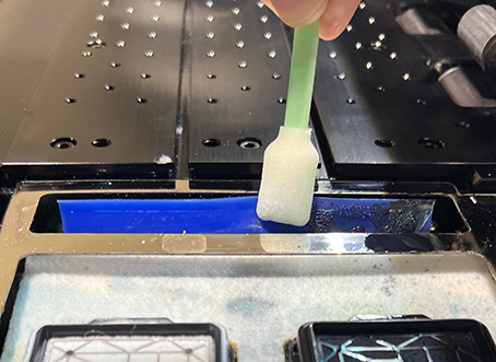
Clean the wiper blade using an anti-static foam swab or microfiber cloth wetted with Super Cleaner.
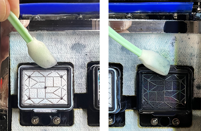
Clean the capping station seals using Super Cleaner on an anti-static foam swab or microfiber cloth.
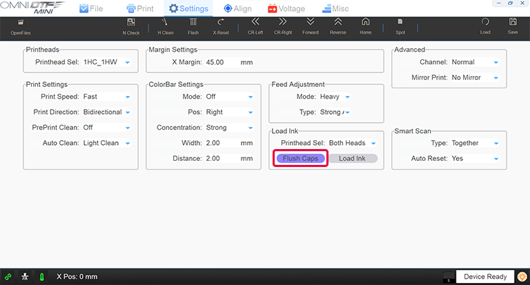
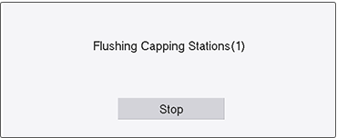
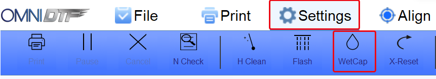
Flush out the capping stations by clicking the Flush Caps button on the Settings screen of the Omni DTF Mini UI software, then squirting Super Cleaner from the squeeze bottle into each capping station to rinse out any ink residue.
Click the Stop button once the capping stations are free of ink residue.
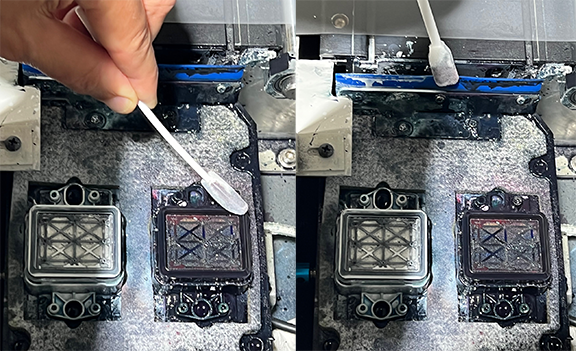
Clean the undercarriage around the printheads by opening the front-left access panel door.
Use a foam swab or microfiber cloth wetted with Super Cleaner to wipe off any accumulating ink.
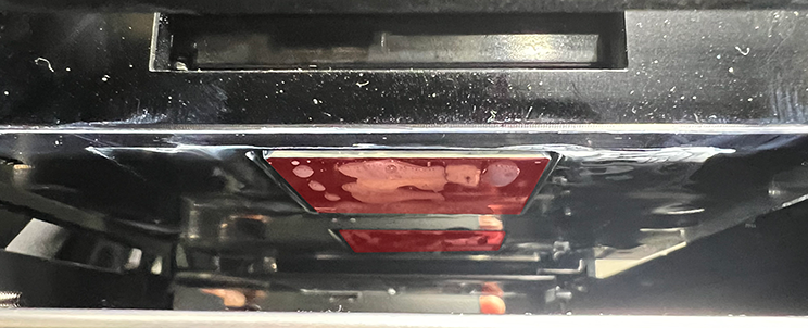
Be careful to clean only the printheads mounting bracket and the side edges of the printheads, and not the nozzle plate (shown with a red tint below).
Wet cap the printer by filling the capping stations with Super Cleaner…
…then pressing the printer’s Enter key or clicking the Omni DTF Mini UI program’s Home icon.
Consumable parts are those parts expected to require replacement during the warranty period through no fault of the part’s quality or the manufacturing process. For examples of consumable parts in general, car owners will be familiar with the concept as it applies to tires, brakes, oil filters, air filters, windshield wipers, etc.
Like any piece of industrial equipment with moving parts and fluids, the OmniDTF system includes parts that must be maintained and periodically replaced over time. These are known as “consumables”. Replacement of consumable parts is not covered by the warranty (except in the rare case of defects that occur in brand-new equipment) and should be factored into your operating budget as a normal cost of doing business.
Some consumable parts are critical to the operation and maintenance of the printer. For example, if you have a damper or capping station that leaks air then you may not be able to print or properly wet cap the printer until the problem is resolved.
We recommend keeping spares of consumable parts on-hand to minimize downtime when they do need to be replaced. The most convenient and economical way to ensure that you have a set of consumable parts on hand when you need them is with OmniDTF Support Kit.
The OmniDTF Support Kit
OmniPrint has created a collection of consumable parts into a support kit for the OmniDTF. The idea is to make it easy to place a single order (part number “KITSPRTDTF“) at a discounted price to keep a set of consumable parts on hand.
Having an OmniDTF Support Kit on-hand saves you the administrative and shipping time of placing individual orders for individual parts as they require replacement. In addition to the over 18% cost savings of the kit compared to purchasing the parts individually, eliminating the downtime of waiting for a part to arrive and the cost of multiple shipments for each individual part is a solid investment in keeping your operation running efficiently and at maximum production.
OmniDTF Support Kit Contents
Here are the parts included in the OmniDTF Support Kit in a simple table. Images of each part will be shown below the table.
Qty.
Description
Part Number
1
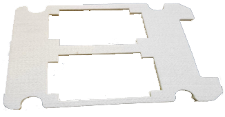
DTF Absorbing Pad
P-DTF3041
1
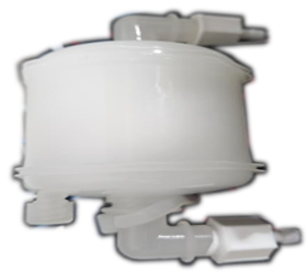
DTF White Ink Circulation Filter
P-DTF4024
8
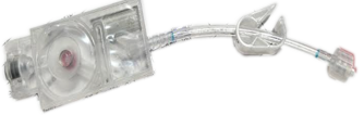
i3200 Damper Assembly (preassembled damper, tubing, clip, and quick-connect fitting)
P-i2OM1003
1
Capping Station Set (‘2’ capping stations, preassembled with Tygon tubing)
P-DTF4086
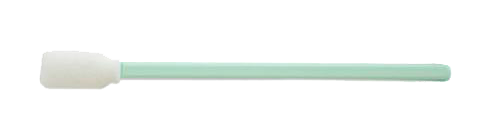
10
Freejet Swabs
P-MC1007
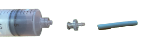
1
Syringe, including adapter piece for dampers
P-MC1004
1
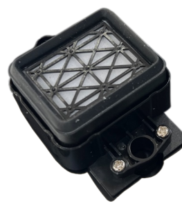
Freejet Grease canister, 7g
P-FJG7G
1
Wiper Blade
P-DTF6001
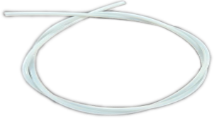
6 ft
Teflon tubing for ink line
P-DTF3040
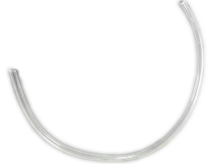
3 ft
Tygon tubing for ink line interconnections
P-CB1032
OmniDTF Absorbing Pad
White Ink Circulation Filter
Damper Assembly
Capping Station (‘2’ in Support Kit, included tubing not shown)
This video demonstrates and explains how to properly clean the encoder strip.
Remember to use only 70% isopropyl alcohol and a lint-free cloth or soft paper towel for the cleaning procedure. Use of any other cleaning fluid or agent may damage the marking on the encoder strip, requiring that it be replaced.
As mentioned in the OmniDTF System Shutdown article (linked at the bottom of this page), performing proper maintenance and wet capping the printer when shutting it down is critical to maximizing the service life of your printheads, capping stations, and wiper blade.
The process detailed in that article requires using the OmniDTF UI software to wet cap the printheads after completing the shutdown maintenance. Moving the carriage away from its home position can be done from the printer’s control pad or the OmniDTF UI program.
But what if you experience a power failure or your PC has lost its ability to communicate with the printer for some reason?
In the below video and the following instructions, we explain how to manipulate the capping station platform and the carriage to allow performing shutdown maintenance and wet capping the printer manually in the event of a power failure or any situation that prevents normal use of the controls and software.
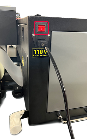
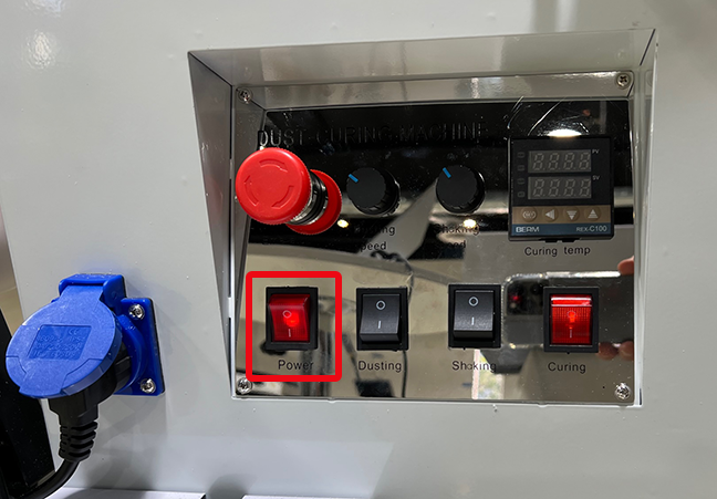
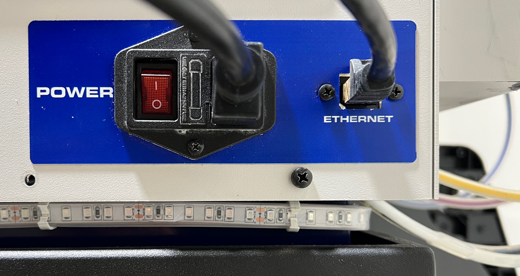
Turn off the power switch on the printer before proceeding if you have lost power. This is done to ensure that the printer doesn’t suddenly come back on if power is restored. Mechanical movement during the printer’s initialization could injure someone in the middle of performing maintenance and also damage the printer. It is also recommended to turn off the curing oven to ensure that it doesn’t come back on and heat up while unattended.
Demonstration video
Your PC Can’t Wet Cap the OmniDTF
If you have not lost power and the printer’s control panel is working fine but you can’t complete the wet cap process from the OmniDTF UI software on your PC for any reason, follow the usual shutdown procedure until it’s time to click on the software’s WetCap icon. At that point, follow the instructions near the end of this article for Manually Wet Capping the Printheads.
The Printer Has No Power
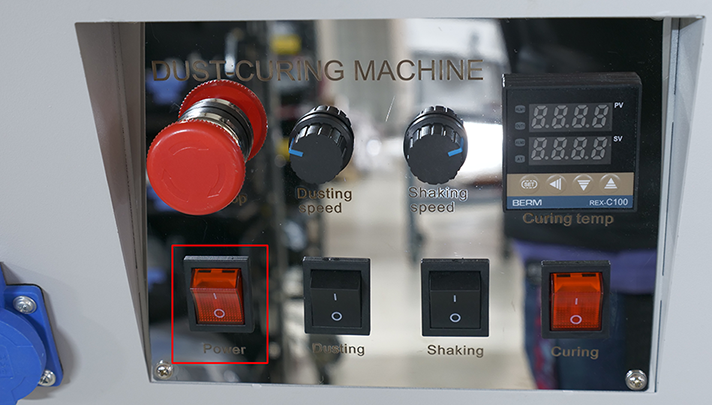
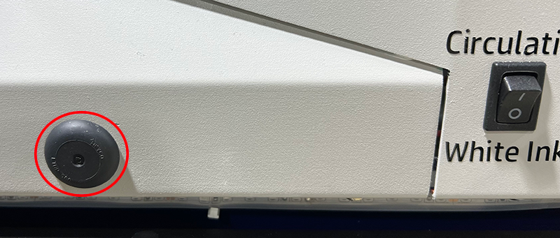
If you have lost power, first make sure the Emergency button hasn’t been accidentally depressed by rotating it about ¼ turn clockwise. That will release the button and restore power if it had been depressed.
If the Emergency button was not depressed, either power is no longer being provided by the outlet or the printer’s power system needs troubleshooting. In either case, we want to ensure that the printer’s carriage will not move if power is restored while you’re working on it by turning off the printer’s power switch. Optionally, you can also unplug the power cable.
The Dust-Curing Machine’s master Power switch or its oven’s ‘Curing’ switch (for power to the oven) should also be turned off, to prevent it from coming back on while potentially unattended when power is restored.
Manually Releasing and Undocking the Printhead Carriage
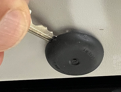
Remove the small, black rubber plug covering a hole below the printer’s control pad and locate the screw head on the other side of the hole(s) exposed by removing the plug(s).
If your printer has two rubber plugs below the control pad, remove both and identify which is best aligned with the screw.
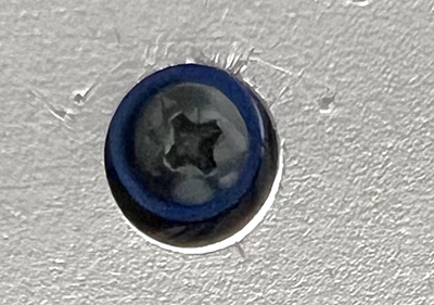
Identify whether the head of the screw in your printer has a Phillips or Allen-type head.
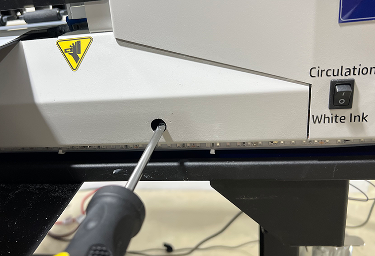
Rotate the screw counterclockwise to lower the capping station platform until it can turn no further in that direction.
Remove the right side window for a clear view of the side of the capping station platform to visually confirm the capping stations’ downward movement.
After the capping stations are fully lowered, manually push the carriage to its fully leftward position to perform the routine shutdown maintenance.
Confirm that the carriage is all the way to the left as far as it can go. If it is positioned over the platen, the heat rising from the platen heater can cause the ink in the printhead nozzles to dry out and clog them.
With the carriage at its full left position, you can now perform all of the routine shutdown maintenance steps.
Manually Putting the Carriage in its Home Position
The printhead carriage’s Home position is not its fully-right position. That would be too far right and the nozzle plates and capping stations may not be properly aligned.
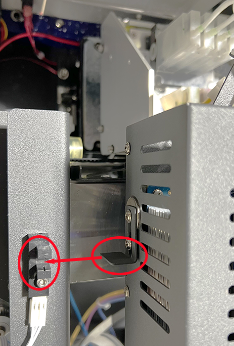
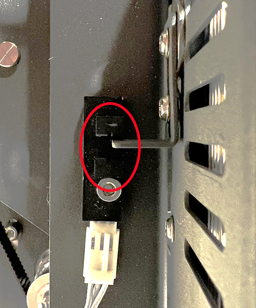
Use the metal tab on the right side of the printhead carriage and the slotted sensor on the carriage frame to find the Home position. The correct carriage position is when its tab reaches the assembly’s sensor window, at the mid-point of the slot.
Position the carriage so the end of the metal tab just reaches the center of the sensor’s gap.
Manually Wet Capping the Printheads
At this point, you should have already performed the shutdown maintenance, filled the capping stations with Super Cleaner, and moved the carriage to its Home position. If not, do that now before continuing.
If your printer and its control panel are working fine but you need to manually wet cap the printer because you can’t do it from the OmniDTF UI program on a PC, push the Enter button on the printer’s control pad to put the printhead carriage in its Home position, then turn off the printer’s power before proceeding.
Remove the black rubber plug(s) under the printer’s control pad, if you haven’t already done so. (See steps 1 & 2 in the Manually Releasing and Undocking the Printhead Carriage section above.)
Use a Philips head screwdriver or Allen wrench (depending on the screw head behind the exposed hole) to rotate the screw clockwise while looking through the opening made by removing the right side window to watch the capping station platform rise.
Continue rotating the screw until the capping station presses against the bottom of the printhead, then raise it about another 1/4″ or so to compress the capping station seals against the printhead plate.
The printer is now properly shut down and wet capped when the above steps have been completed.
If you haven’t already done so, this is a good time to empty the waste ink bottle and confirm that all of the ink clips are closed.
You will occasionally want to adjust the printhead alignment of your OmniDTF or Omni DTF Mini printer, to maintain ideal horizontal & vertical registration between the color and white layers of your prints. This adjustment does not involve manually repositioning the printheads. Instead, it is done using the provided UI software.
If the vertical registration of your OmniDTF is off, be sure to first check the tension of the feed roller knobs on the back of the printer and make sure the left and right sides are at their minimum tension/friction settings before making a vertical printhead alignment adjustment. This mechanical adjustment is critical and too much tension may cause random vertical registration issues that cannot be resolved by the software alignment of the printheads described below.
The process is identical for the OmniDTF and the Omni DTF Mini printers. View the below video or read the following instructions for each step of the printhead alignment process.
Print Speeds
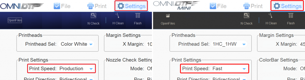
There are three Print Speed settings for the OmniDTF & DTF Mini printers. In both cases, we recommend using the default setting, which is the fastest speed.
All printhead alignment adjustments are made for a given Print Speed, so the print speed selected for alignments should be the same as the print speed selected for printing on the Settings tab.
On the OmniDTF the default and fastest speed is named “Production” and on the Omni DTF Mini the default and fastest speed is named “Fast”.
Print Speed default setting names on the OmniDTF (left) and Omni DTF Mini (right)
The UI software’s default Print Speed of Production (on the OmniDTF) or Fast (on the Omni DTF Mini) are recommended and deliver the fastest output at any Environment selection in the Print Pro RIP software.
Alignment Types
There are four types of alignments that can be done. We’ll explain and detail the process for each following the list of types below:
Head Vertical Distance Adjustment
Head Horizontal Distance – Left Adjustment
Head Horizontal Distance – Right Adjustment
Bidirectional Adjustment
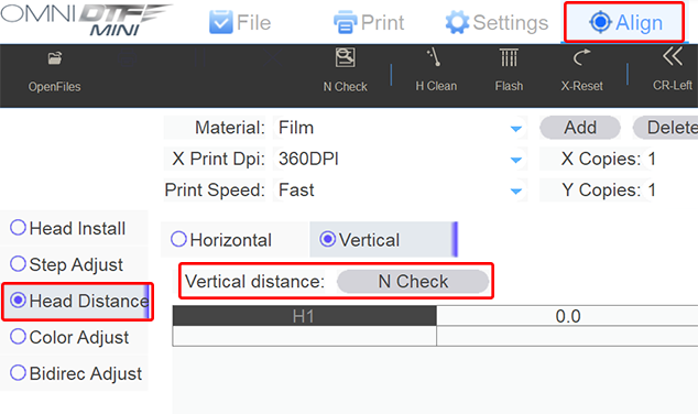
To get started, all printhead alignment adjustment types are found under the Align tab of OmniDTF UI program.
Head Vertical Distance
This adjustment, labeled Head Vert Distance Adjust in the software, aligns the white printhead with the CMYK printhead as the film moves forward while printing. (This “vertical” movement of the film is considered the Y axis, while the carriage’s left & right motion is considered the X axis.)
Select your Print Speed to match that on your Settings tab (or the speed you want to now align for if you’re running alignments for multiple speeds.)
Select the Head Distance option on the left side of the Align screen.
Click the N Check button under the Head Vert Distance Adjust heading when you’re ready to print the test pattern.
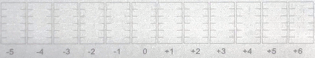
The test pattern prints a series of black & white horizontal line segments above numbered labels. The numbers range from -14 to +14, in increments of 2 and with zero in the center position.
Vertical Alignment test print example (partial, on OmniDTF)
While the alignment process on the OmniDTF and the Omni DTF Mini printers is identical, the test pattern for the vertical alignment is slightly different. So we’ll also show the pattern printed on the Omni DTF Mini, as well.
Vertical Alignment test print example (partial, on Omni DTF Mini)
Yes, it’s a bit of an eye test, but our task is to identify the column number whose line segments show the black & white portions in best alignment with each other, resulting in a single straight horizontal line. In the first of the two above examples (printed on the Omni DTF), the best column is ‘+4’.
In the ‘+2’ column the white segments are slightly below the black segments, and in the ‘+6’ column the white segments are slightly above the black segments. As you look to the left of the ‘+2’ column you can see that the white segments keep getting further below the black segments and to the right of the ‘+6’ column the white segments keep getting further above the black segments.
So, our takeaway from the evaluation of the test print is that the column with the best alignment is ‘+4’.
Now let’s return to the OmniDTF UI software’s Head Vert Distance Adjust section and note the current value of H2. In our screenshot from step #2 above, the value of H2 is “1453” and the number we got from evaluating the test print in step #3 was ‘+4’, so we add ‘4’ to ‘1453’ and enter the result of 1457 into the H2 field.
If the column number from step #3 had been a negative number (‘-4’, for example), we would have subtracted ‘4’ from ‘1453’ and entered ‘1449’ into H2.
Click the Save button in the top right corner of the OmniDTF UI window to make the alignment adjustment.
Repeat step #3 above to print another test pattern. This should result in the best-aligned column sitting in the ‘0’ position. If this is the case, the vertical distance adjustment is now completed. If not, repeat steps 3 – 5 to ensure that the best alignment is in the ‘0’ position
Left Horizontal Distance
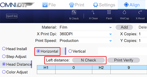
There are two horizontal distance adjustments under the Head Horz Distance Adjust heading. This is because your OmniDTF prints bidirectionally, so the white and CMYK printheads need to be aligned in both printing directions. The Left Adjust is used for the horizontal alignment when the carriage is moving from right to left, and the Right Adjust for when the carriage moves from left to right.
The process and test patterns for both the Left and Right printhead horizontal distance alignment adjustments are identical, so we will detail the process just once. The instructions will call out the Left Adjust button and H2 field, and you will follow these same steps modified for the Right Adjust button and H2 field for the Right Horizontal Distance Adjustment.
Click the Left distance N Check button to run a test print.
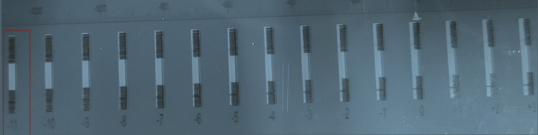
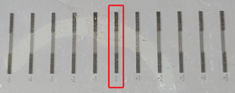
The test pattern prints a series of black & white vertical bars above numbered labels. The numbers range from -12 to +12 with zero in the center position.
The goal is to have the best-aligned set of black & white bars in the 0 (zero) position. So, our takeaway from the evaluation of the test print is that the column with the best alignment is ‘-11’.
Now let’s return to the OmniDTF UI software’s Head Horz Distance Adjust section and note the current value of H2. In our screenshot from step #1 above, the value of H2 (for the Left Adjust line) is “9”. The number we got from evaluating the test print was ‘-11’, so we sum together ‘9’ (or ‘+9’, to be exact) with ‘-11’ and enter the result of ‘-2’ into the H2 field…
…then click the Save button.
Repeat step #1 above to print another test pattern. This should result in the best-aligned column sitting in the ‘0’ position.
With the 0 (zero) position of the test print showing the black & white segments in perfect alignment, the Printhead Horizontal Distance Adjustment (for the leftward motion, in this example) is now complete.
Right Horizontal Distance
The exact same process as the Left Horizontal Distance Adjustment is used to check and adjust the rightward motion alignment.
Follow the instructions from the above Left Horizontal Distance Adjustment section, substituting the Right Adjust button to run test prints and the Right AdjustH2 field to enter updates to that value, as needed.
Bidirectional
Our final task is to align the printheads during bidirectional printing (both left and right.)
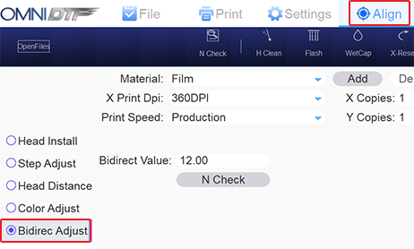
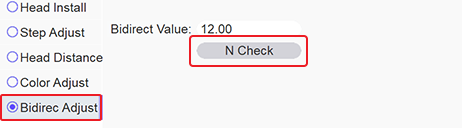
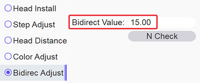
Select Bidirec Adjust from the options on the left side of the OmniDTF UI program.
Click on the N Check button to print a test pattern.
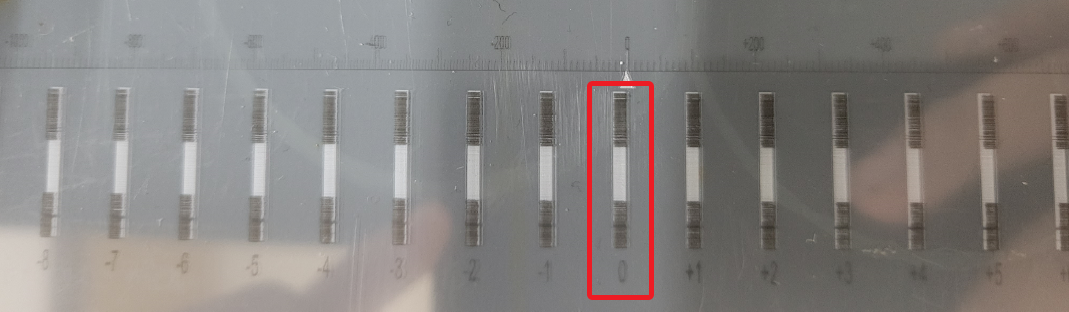
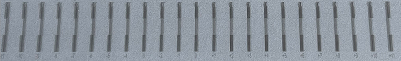
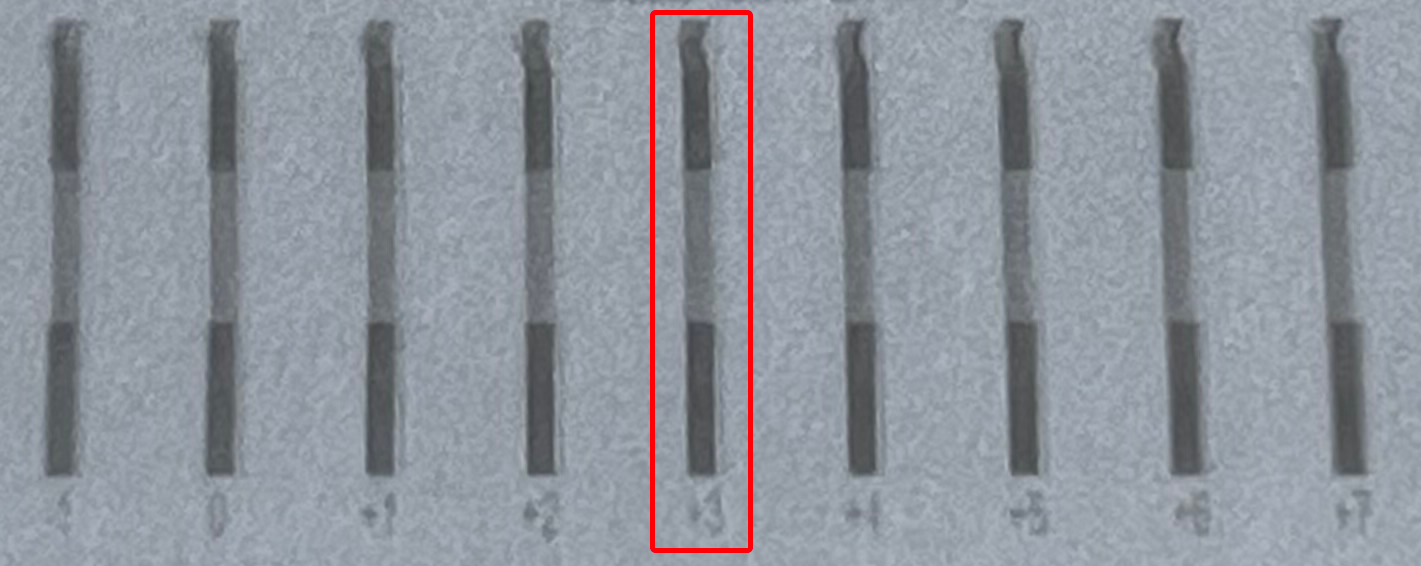
The Printhead Bidirectional Alignment Adjustment test pattern will print.
The vertical bar test pattern has top & bottom black segments and a grey middle segment.
Our task now is to identify the number under the test bar where the middle segment is best aligned with the top & bottom segments, creating a straight vertical bar with the right & left edges of each of the three vertical segments perfectly aligned.
In our example test print image above, the ‘+3’ column is vertically aligned.
Returning to the OmniDTF UI program, we take that value (‘+3’) and sum it with the number in the direct Value field (‘12.00’ in the above screenshot example.) 12+3=15, so we will replace the value of ‘12.00’ with ’15’.
…and then click the Save button in the upper right corner.
Click the N Check button again to print another test pattern and confirm that the vertical segments are perfectly aligned at the 0 (zero) position.
With the 0 (zero) position of the test print showing the black & gray segments in perfect alignment, the Printhead Bidirectional Adjustment is now complete.
Wrap Up
Congratulations! If you’ve been following along on your OmniDTF printer while reading this article you have now completed all four printhead alignment processes: the Vertical Distance, Left Horizontal Distance, Right Horizontal Distance, and Bidirectional Adjustments.
Remember that these adjustments are each made with a specific Print Speed setting, so if you print using different speed selections at different times then you’ll need to repeat this process for each speed that you use.
Properly shutting down your OmniDTF printer is very important to ensure that it will be ready to print the next time you start it up. Fortunately, the process is very easy!
Take about 10 minutes to go through these simple steps when you’re finished with your print jobs.
Wet capping the printheads after completing the shutdown maintenance steps is critical to prevent ink from drying in the printhead nozzles, potentially clogging them permanently.
Click the Related Articles link at the bottom of this page if you are experiencing a power outage, printer hardware issue, or PC connectivity problem preventing you from following the instructions below.
Curing Oven Shutdown
If you haven’t already done so, start by turning off the Curing Oven’s main power switch. This is a master switch that will cut power to the Duster, Shaker, and Oven — so shutting off any other switches is optional.
Printer Shutdown Maintenance & Wet Capping
See the below video demonstrating the OmniDTF printer shutdown maintenance and wet capping processes, or read the following description.
Demonstration video
Please also see the Prepare for Success section below after viewing the video for tips on minimizing your startup time and keeping your white ink in top shape.
Step-by-step instructions
Press and hold the Carriage Left button until the printhead carriage is in the center of its range of motion to ease access to the ink clips and expose the capping stations and wiper blade.
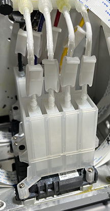
Clamp all 8 of the ink line clips shut.
Use the Carriage Left button again to move the printhead carriage to its full-left position.
Wet an anti-static foam swab or a clean, lint-free cloth with Super Cleaner to thoroughly clean:
The full length of the wiper blade
The rubber seals surrounding both capping stations
Remove any bits of dried ink on the capping station sponges or seals with tweezers.
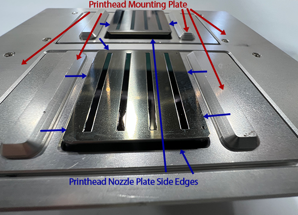
The remainder of the steps before wet capping the printhead are all about keeping the printhead mounting plate and the side edges of the printhead nozzle plates clean. If these areas are allowed to accumulate ink then eventually the dried ink will hang down below the printhead and leave streaks on the film.
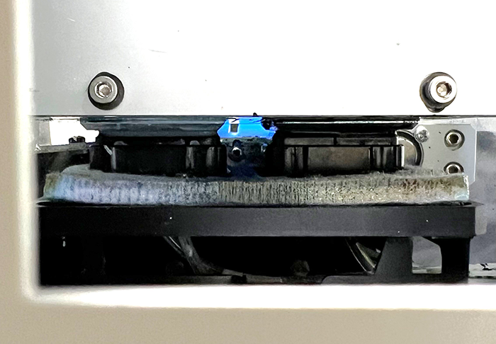
Before continuing this maintenance process, please note the following images of the shape and relationship of these parts to each other, and examples of how they may appear before and after cleaning.
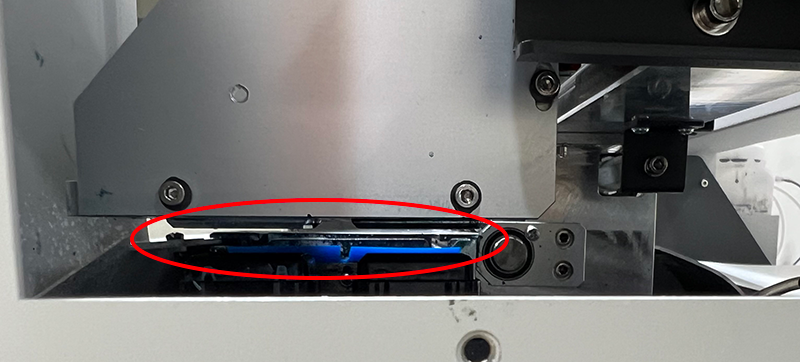
Area of printhead mounting plate and nozzle plate edges to be cleaned. Bottom of printhead mounting plate with printheads installed. Red arrows point to areas of the mounting plate; blue arrows point to the nozzle plate side edges
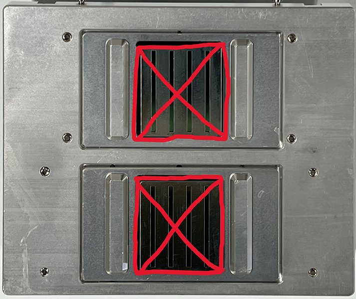
Areas of the printhead nozzle plate cleaned by the wiper blade, not manually Red X’s mark the face of the nozzle plates, an area that we don’t clean manually.
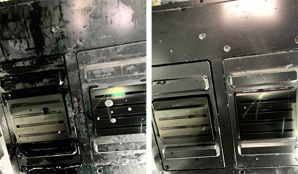
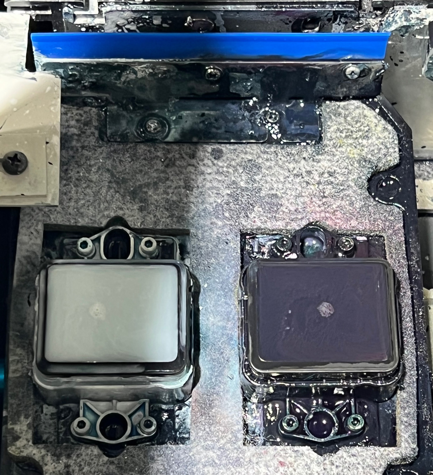
Before & After examples of dirty and clean mounting plates and nozzle plate edges Cleaning the mounting plate and nozzle plate edges daily prevents ink buildup.
Now that you’re familiar with the area we’ll be working with, let’s proceed with cleaning the mounting plate and the side edges of the printhead nozzle plate.
Remove the left-side window to access the chassis interior’s left side. Left side of OmniDTF printer with the window panel removed.
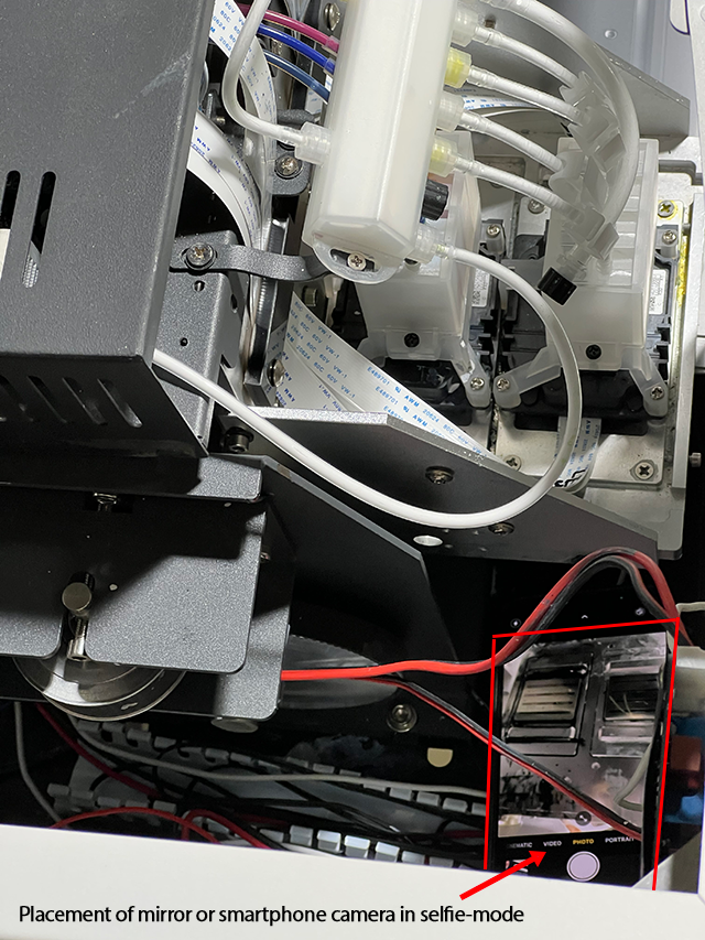
Place a mirror or smartphone camera in selfie-mode inside the front-left corner of the printer chassis, tilted at an angle to provide you with a view of the printhead plates and their mounting plate, which face downward on the bottom of the printhead carriage, to orient yourself and get your hand into position to begin cleaning the area.
Top-down view of a smartphone in selfie-mode tilted at an angle to display the printhead mounting plate and the printhead nozzle plates.
Use a clean, lint-free cloth dampened with Super Cleaner to reach under the printhead carriage and wipe any ink from the mounting plate and the side edges (only) of the printhead nozzle plates.
A foam swab can be used to clean the area at the front of the white ink printhead if a cleaning cloth wrapped around a finger won’t fit in the space.
If contact with the printhead’s nozzle plate is made accidentally, dab the contacted area with Super Cleaner on a clean, lint-free cloth before wet capping.
Wet Capping the Printhead
Fill both capping stations to the brim with Super Cleaner.
The wiper blade and capping station seals should now be free of any ink build-up and the capping station sponges completely submerged in Super Cleaner, up to the top of their seals.
Click the WetCap button under the Settings tab in the OmniDTF Windows program.
This will send the printhead carriage to its docked position and raise the capping station seals to press against the bottom of the printhead plate, bathing it in Super Cleaner within an air-tight seal.
The printer can now be turned off from the power switch on the right side, near the back of the printer.
The printhead maintenance components have now been cleaned and the printhead is wet capped.
Prepare for Success
We recommend two more steps to wrap up your shutdown process by preparing your printer in advance for the next day of printing.
Empty the waste ink bottle for a fresh start next time the printer is used.
Agitate the white ink to mix any separating pigment and prevent sediment from collecting in the bottom of the white ink bottles.
Press a clean cloth or finger against the ink bottles’ breather hole to avoid spillage.
Shake the bottle aggressively for 15-30 seconds to thoroughly mix the ink.
When finished, use a clean cloth to wipe away any ink that appears to be blocking the breathing holes in the center of the bottle caps.
We can also shake the white ink during the startup process, and will want to do that if the printer has been idle for several days. However, shaking the white ink will result in small bubbles forming so we need to wait at least 15-30 minutes after shaking before circulating the white ink or printing.
If using the OmniDTF nearly every day, shaking the white ink at the end of a printing day, rather than at the beginning, helps to keep the pigment mixed while not delaying the startup process next time we want to use the printer.
That’s all there is to it. Your printer is now well-maintained and ready for your next day of printing.
Performing the recommended maintenance is the most important factor in maximizing your equipment’s service life and consistently getting high-quality prints.
We recommend using the daily, weekly, and periodic maintenance log sheets for your printer and pretreatment machine (PDF download links below), to help you and your staff track and manage your equipment maintenance schedules.
Consistently performing the recommended steps at the beginning and end of each printing day will go far to prevent interruption of your production work that could otherwise occur due to insufficient maintenance.
Staying on top of the daily, weekly, and other periodic preventative maintenance also helps to maximize the service life of the equipment and protect your warranty.