In the below video and the following step-by-step instructions, we demonstrate how to rip an image or Layout to get the ink cost without printing. We’ll also show you how to save the ripped Layout to a file, including all sizing and configuration settings, and also how to load a previously saved rip for immediate printing.
Rip Without Printing
Once you have images and Layouts fully configured and ready to print, it’s simple to rip them without printing. Features of Print Pro’s Queue Manager can then be used to do things like determine the cost of ink needed to print the rip or to save the fully configured rip and quickly load and print it in the future.
For a refresher on how to set up images and Layouts see the Setting Up a Print knowledge base article.
Here’s how to rip an image or Layout in Print Pro.
First complete your image(s) and Layout setup, including sizing and creating the white underbase choke for the images.
Place the image(s) onto a Layout if you want to rip the full Layout.
Select the image or Layout you want to rip by clicking on it.
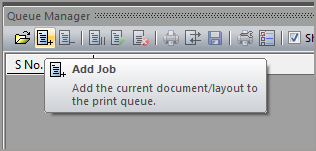
Click on the Add Job icon in the Queue Manager toolbar — the 2nd icon from the left.
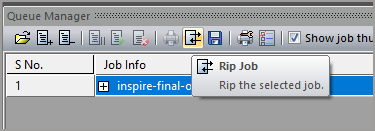
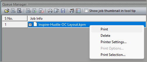
Right-click on the new item added under the Queue Manager’s Job Info heading, then click on Rip. You may instead select the new line, then click the Rip Job icon on the Queue Manager toolbar — the 8th icon from the left.
Queue Manager’s Status column will display “Ripping…” as it begins ripping the job. This message will change to “RipDone” when the rip is finished.
Viewing Ink Costs of a Ripped Job
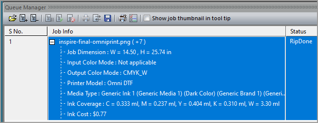
Click on the ‘+’ symbol to the left of the ripped job’s name in Queue Manager’s Job Info column.
Scroll down the expanded view in the Job Info column to find the amount and cost of each ink color used in the design, as well as the total ink cost.
Saving a Ripped Job
Saving a ripped job is a two-step process. We first tell the software where we want the file to be saved, then we save it.
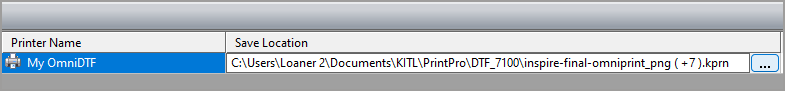
Review the Save Location for the ripped file in the far right column of Queue Manager. If you want to save the rip to the currently designated location, skip to step 5.
Under the Save Location heading, click on the line of the ripped job that you want to save.
Click on the ellipses (“…”) that appear at the right end of the line that you clicked on.
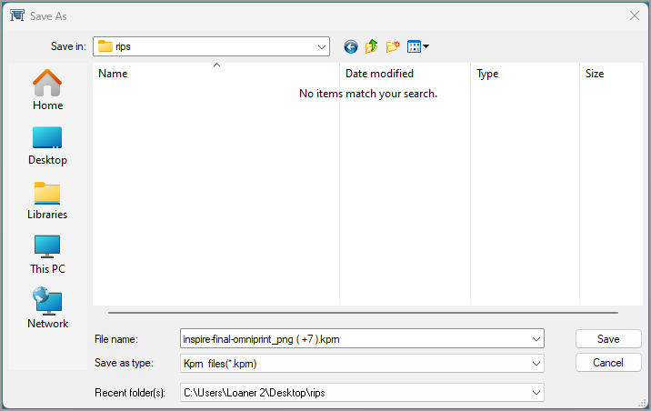
In the “Save As” window that appears, navigate to the folder where you want the rip to be saved, and click on the Save button. This does not save the rip. It simply lets you edit the filename to be used and saves the location where the rip will be saved when you do save the rip in the next step.
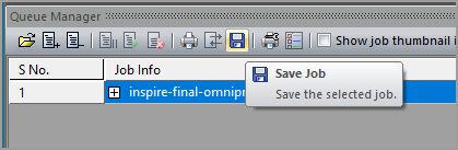
Click on the Queue Manager’s Save Job button (a disc icon) to save the rip to your designated location.
Loading a Saved Rip
Loading a saved rip is quick and easy. Since all image and Layout parameters were included when the ripped file was saved, once the rip is loaded it can be immediately printed.
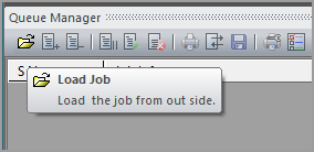
Click on Queue Manager’s Load Job icon. The first icon from the left, with the appearance of an open folder.
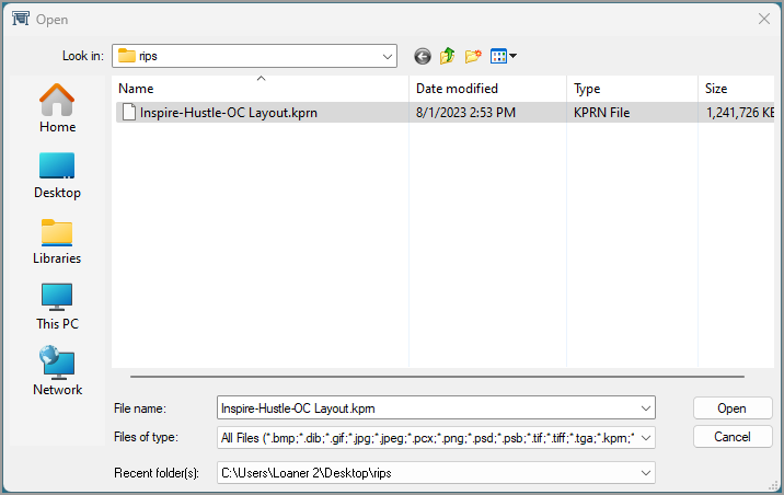
In the File Open window that appears, navigate to the folder where the rip file you want to print was stored, then select the rip file and click Open.
When the saved rip appears in Queue Manager’s Job Info column, right-click on it and select Print or click on the Print Job icon in Queue Manager’s toolbar.
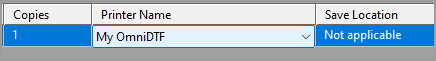
If the print options are grayed out, ensure your printer is selected in Queue Manager’s Printer Name column.
As mentioned in the OmniDTF System Shutdown article (linked at the bottom of this page), performing proper maintenance and wet capping the printer when shutting it down is critical to maximizing the service life of your printheads, capping stations, and wiper blade.
The process detailed in that article requires using the OmniDTF UI software to wet cap the printheads after completing the shutdown maintenance. Moving the carriage away from its home position can be done from the printer’s control pad or the OmniDTF UI program.
But what if you experience a power failure or your PC has lost its ability to communicate with the printer for some reason?
In the below video and the following instructions, we explain how to manipulate the capping station platform and the carriage to allow performing shutdown maintenance and wet capping the printer manually in the event of a power failure or any situation that prevents normal use of the controls and software.
Turn off the power switch on the printer before proceeding if you have lost power. This is done to ensure that the printer doesn’t suddenly come back on if power is restored. Mechanical movement during the printer’s initialization could injure someone in the middle of performing maintenance and also damage the printer. It is also recommended to turn off the curing oven to ensure that it doesn’t come back on and heat up while unattended.
Demonstration video
Your PC Can’t Wet Cap the OmniDTF
If you have not lost power and the printer’s control panel is working fine but you can’t complete the wet cap process from the OmniDTF UI software on your PC for any reason, follow the usual shutdown procedure until it’s time to click on the software’s WetCap icon. At that point, follow the instructions near the end of this article for Manually Wet Capping the Printheads.
The Printer Has No Power
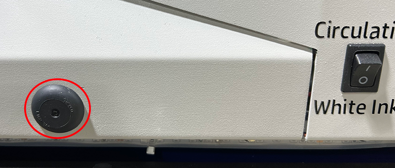
If you have lost power, first make sure the Emergency button hasn’t been accidentally depressed by rotating it about ¼ turn clockwise. That will release the button and restore power if it had been depressed.
If the Emergency button was not depressed, either power is no longer being provided by the outlet or the printer’s power system needs troubleshooting. In either case, we want to ensure that the printer’s carriage will not move if power is restored while you’re working on it by turning off the printer’s power switch. Optionally, you can also unplug the power cable.
The Dust-Curing Machine’s master Power switch or its oven’s ‘Curing’ switch (for power to the oven) should also be turned off, to prevent it from coming back on while potentially unattended when power is restored.
Manually Releasing and Undocking the Printhead Carriage
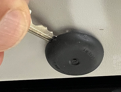
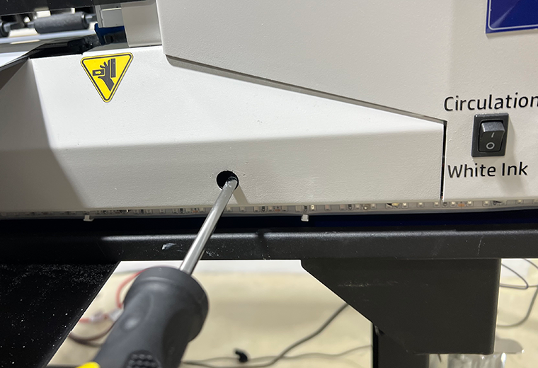
Remove the small, black rubber plug covering a hole below the printer’s control pad and locate the screw head on the other side of the hole(s) exposed by removing the plug(s).
If your printer has two rubber plugs below the control pad, remove both and identify which is best aligned with the screw.
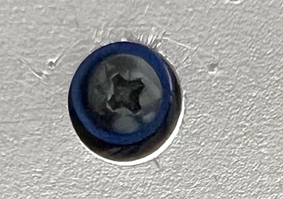
Identify whether the head of the screw in your printer has a Phillips or Allen-type head.
Rotate the screw counterclockwise to lower the capping station platform until it can turn no further in that direction.
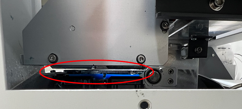
Remove the right side window for a clear view of the side of the capping station platform to visually confirm the capping stations’ downward movement.
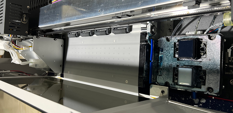
After the capping stations are fully lowered, manually push the carriage to its fully leftward position to perform the routine shutdown maintenance.
Confirm that the carriage is all the way to the left as far as it can go. If it is positioned over the platen, the heat rising from the platen heater can cause the ink in the printhead nozzles to dry out and clog them.
With the carriage at its full left position, you can now perform all of the routine shutdown maintenance steps.
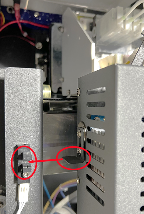
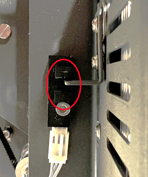
Manually Putting the Carriage in its Home Position
The printhead carriage’s Home position is not its fully-right position. That would be too far right and the nozzle plates and capping stations may not be properly aligned.
Use the metal tab on the right side of the printhead carriage and the slotted sensor on the carriage frame to find the Home position. The correct carriage position is when its tab reaches the assembly’s sensor window, at the mid-point of the slot.
Position the carriage so the end of the metal tab just reaches the center of the sensor’s gap.
Manually Wet Capping the Printheads
At this point, you should have already performed the shutdown maintenance, filled the capping stations with Super Cleaner, and moved the carriage to its Home position. If not, do that now before continuing.
If your printer and its control panel are working fine but you need to manually wet cap the printer because you can’t do it from the OmniDTF UI program on a PC, push the Enter button on the printer’s control pad to put the printhead carriage in its Home position, then turn off the printer’s power before proceeding.
Remove the black rubber plug(s) under the printer’s control pad, if you haven’t already done so. (See steps 1 & 2 in the Manually Releasing and Undocking the Printhead Carriage section above.)
Use a Philips head screwdriver or Allen wrench (depending on the screw head behind the exposed hole) to rotate the screw clockwise while looking through the opening made by removing the right side window to watch the capping station platform rise.
Continue rotating the screw until the capping station presses against the bottom of the printhead, then raise it about another 1/4″ or so to compress the capping station seals against the printhead plate.
The printer is now properly shut down and wet capped when the above steps have been completed.
If you haven’t already done so, this is a good time to empty the waste ink bottle and confirm that all of the ink clips are closed.
The OmniDTF has a robust set of hardware controls, making it simple and convenient to operate most routine functions directly from the printer itself. Here’s a brief rundown on the position and function of each of these controls.
Printer Controls
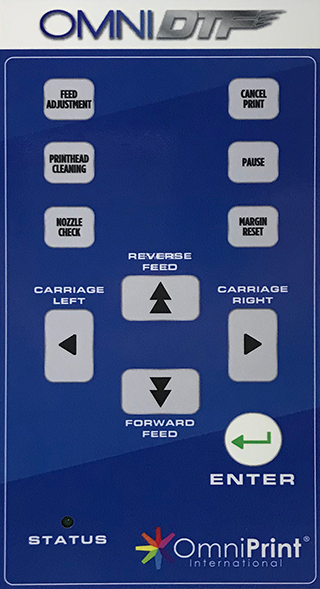
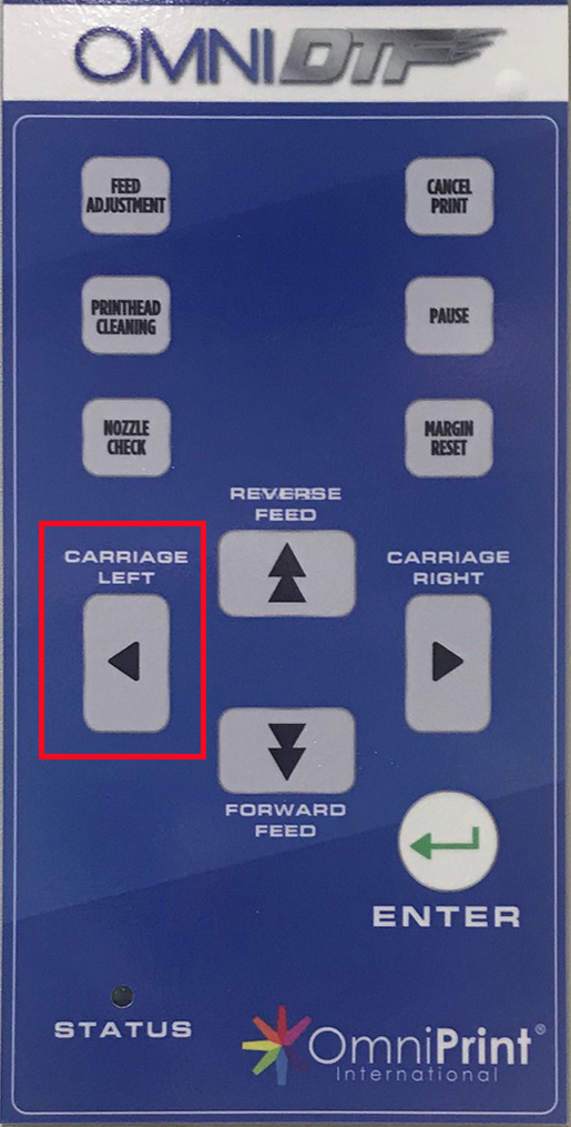
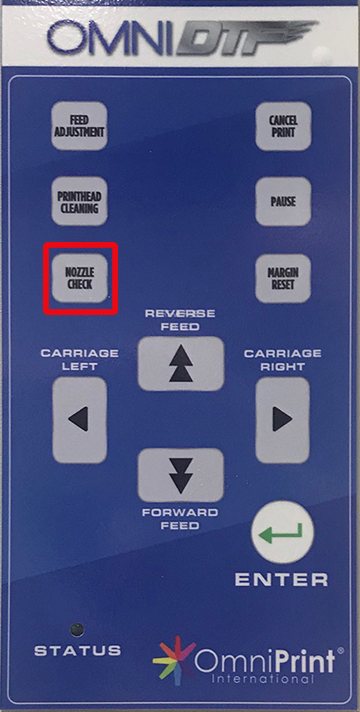
Control Pad
This is the set of pressure-sensitive buttons on the front of the printer, to the right of the platen.
Feed Adjustment: Adjust vertical feed between print passes (use only as directed by Omniprint staff.)
Printhead Cleaning: Run a Light printhead cleaning on both printheads.
Nozzle Check: Print a test pattern to confirm that ink flow is optimal and ready to deliver quality prints.
Cancel Print: Stop printing and remove the remaining print job from the printer’s memory.
Pause: Temporarily stop printing. Pushing Pause a second time will prompt you to continue printing.
Margin Reset: Change the right margin from the default of 10mm (use only as directed by Omniprint staff.)
Carriage Left / Carriage Right: Move the printhead carriage to the left or to the right of its current position. Hold the button for continual movement.
Reverse Feed / Forward Feed: Feed film forward (toward the front of the printer) or backward.
Enter: Submit responses to prompts on the display panel or move the printhead carriage to the Home position (above the capping stations) if there is no prompt
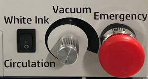
Front Panel Switches
There are three switches positioned directly below the Control Pad. Two of these can generally be thought of as set it and forget it, and the third is essentially an emergency kill-switch. Here are the details.
White Ink Circulation: When toggled to the ON (1) position, white ink is circulated for 1-3 minutes.
Vacuum: This rotary switch turns on and adjusts the suction of the platen’s vacuum. We recommend turning it on and adjusting it to its lowest level for optimal film feeding and platen temperature stability.
Emergency: This red “kill” switch immediately shuts off power to the printer’s electronics when depressed. Once depressed this latching switch will remain engaged and prevent the printer from operating until it is rotated clockwise about ¼ of a turn. It will then pop out and normal operation will be restored.
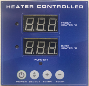
Heater Controller
The Heater Controller is used to adjust and provide status of the OmniDTF printer’s two film heaters. One heater sits behind the platen, to preheat the film as it enters the printer chassis. The second one is under the platen, to keep the film warm as it is being printed on. Heating the film helps the ink set quickly, so the white layer can be applied just seconds after the color layer.
Exceeding the preset temperatures of 40 degrees Celsius for the Front Heater and 50 degrees Celsius for the Back Heater may result in damage to the printheads and/or printer. Damage due to misuse voids the warranty.
Front Heater & Back Heater: The Front Heater and Back Heater numeric displays report each heater’s current temperature in Celsius. When changing the temperature setting, the displays show the changes being selected.
Power: The Power button turns both heaters ON or OFF, toggling their current status. The heaters automatically turn off when the printer is switched off. If the heaters were on when the printer was switched off then they will automatically turn back on when the printer’s power is turned on.
Select: To change a temperature setting for a heater, that heater must first be selected by pushing the Select button, after which the numeric display of the currently selected heater will flash. The first press of the Select button selects the Front Heater. A second press selects the Back Heater. A third press of the Select button exits the temperature adjustment mode.
Temp: The Temp (+) and Temp (-) buttons are used to raise or lower the temperature setting of the currently selected heater.
Dust-Curing Machine Controls
The Dust-Curing Machine has its own power cord and switch, so is plugged into a separate outlet from the printer. While the two pieces of equipment are powered and controlled independently, they form a single, complementary system.
Most of the controls on the Dust-Curing Machine are found on a single control panel on the right side of the equipment. We’ll detail each of those first and then move on to the exceptions.
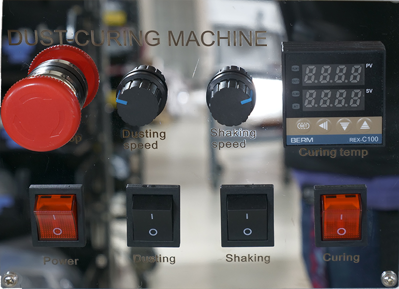
Control Panel
Here you’ll find switches for Power, Dusting, Shaking, Curing, and an Emergency off switch. In addition to these switches, there are also granular controls for setting the dusting speed, shaking speed, and curing oven temperature.
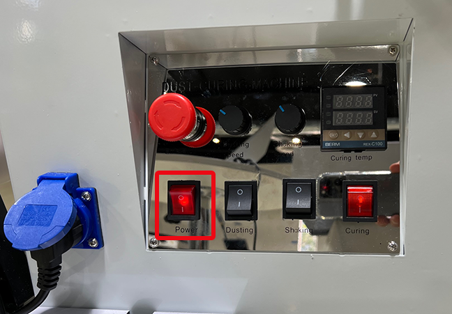
Power Switch
The Power switch in the lower-left corner of the Control Panel is the master power for all other switches and functions of the Dust-Curing Machine. When this switch is OFF, all other switches and controls of the Dust-Curing Machine are inoperable because there is no power being supplied to any part of the unit.
Emergency Switch
The round, red Emergency button above the Power switch will immediately shut off power to the Dust-Curing Machine when depressed.
This is a “latching” switch which, once depressed, will prevent the Dust-Curing Machine from operating until the switch is released. If you ever find that the Dust-Curing Machine won’t turn on from it’s power switch, make sure this switch is not depressed.
To release the switch, rotate the handle clockwise for approximately ¼ turn. Once the switch is rotated clockwise, a spring will push it back out and power will then be restored to the Dust-Curing Machine if, or as soon as the Power switch is in the ON position.
Dusting Switch & Speed control
There are two Dusting controls used to add DTF Powder onto the film as it passes through the powder application chamber.
Dusting switch: This switch toggles the power to the rotating Dusting blades in the DTF Powder Feeder to sweep powder into position to cascade onto the film through narrow slits in the bottom of the powder feeder.
Dusting Speed dial: This dial is used to adjust the rotational speed of the DTF Powder Feeder. The further it is turned clockwise the faster the feeder will rotate and sweep DTF Powder into position to be dusted onto the film.
Shaking Switch & Speed control
There are two Shaking controls used to remove excess DTF Powder from the film after it has been applied by the Dusting feature.
Shaking switch: This switch toggles power to the rotating Shaking spindle with short plastic straps that shake the film as they rotate, shaking any excess DTF Powder back onto wet ink or into the Powder Recycle Bin.
Shaking Speed dial: This dial is used to adjust the rotational speed of the Shaking spindle. The further it is turned clockwise the faster the straps will shake the firm to knock excess DTF Powder loose.
Curing Oven Temperature
There are two controls for the Curing Oven. Remember that using a temperature that will effectively cure the ink and melt the DTF Powder is an important part of the DTF production process. We recommend starting with a setting of 120 Celsius and adjusting from there as needed.
Curing switch: The curing switch turns power for the Curing Oven and the Curing Temp Controller ON and OFF.
Curing Temp Controller: The Curing Temp Controller is used to set and monitor the oven temperature, using four buttons and two numeric displays.
When the Curing power is switched on, the upper display shows the current oven temperature, and the lower display shows the temperature setting.
Changing the temp setting
Set button: Push and hold the Set button until the lower numeric display begins to flash.
◄ button: When in the temperature setting mode (having been activated by the Set button), the temperature setting display shows a cursor in the rightmost column of the setting number.
We recommend making temperature adjustment in 5-degree increments, so for most temperature changes you’ll want to adjust from this rightmost position. To change the setting in increments of 10’s, use this button to move the cursor one digit to the left – to the 10’s position.
▼ button: Use this button to reduce the temperature setting at the cursor position.
▲ button: Use this button to increase the temperature setting at the cursor position.
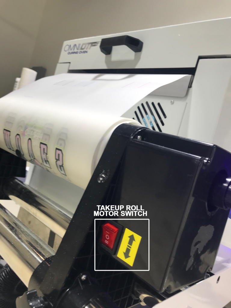
Take-up Roll Motor Switch
This 3-position switch is set to the down position to enable the motor to rotate the take-up roll counter-clockwise (from the perspective of the side of the Dust-Curing Machine controls.) The center position turns the motor off, and the top position is for reverse feeding film backwards, toward the oven and printer.
Remember that the Power switch on the Dust-Curing Machine turns on & off the power to all features of that equipment. If you prefer you can leave the other switches on and just use the main Power switch.
The OmniDTF & DTF Mini printers use the TCP/IP (Transmission Control Protocol/Internet Protocol) over an Ethernet connection to communicate with your PC. This requires a one-time configuration in Windows, which OmniPrint Training sets up for you during your initial training session.
The following information will help you to perform that same configuration if you should ever need to update your PC’s Ethernet adapter or if you’ve reinstalled the OmniDTF UI and Print Pro software onto a new PC.
Your OmniDTF printer and its software implementation are not designed to communicate over the Internet or any other network. We use a simple point-to-point connection between one PC and the printer, directly connected with a single Ethernet (“RJ45”) cable.
There are two pieces of software where we configure TCP/IP parameters: Microsoft Windows (Control Panel) and Print Pro. We’ll cover both in that order.
Microsoft Windows
Windows Control Panel’s Network and Sharing Center is where any Ethernet adapters to be used in a Windows PC are configured. Use the steps in the below video or the following written instructions to configure an Ethernet adapter for use with the OmniDTF & DTF Mini.
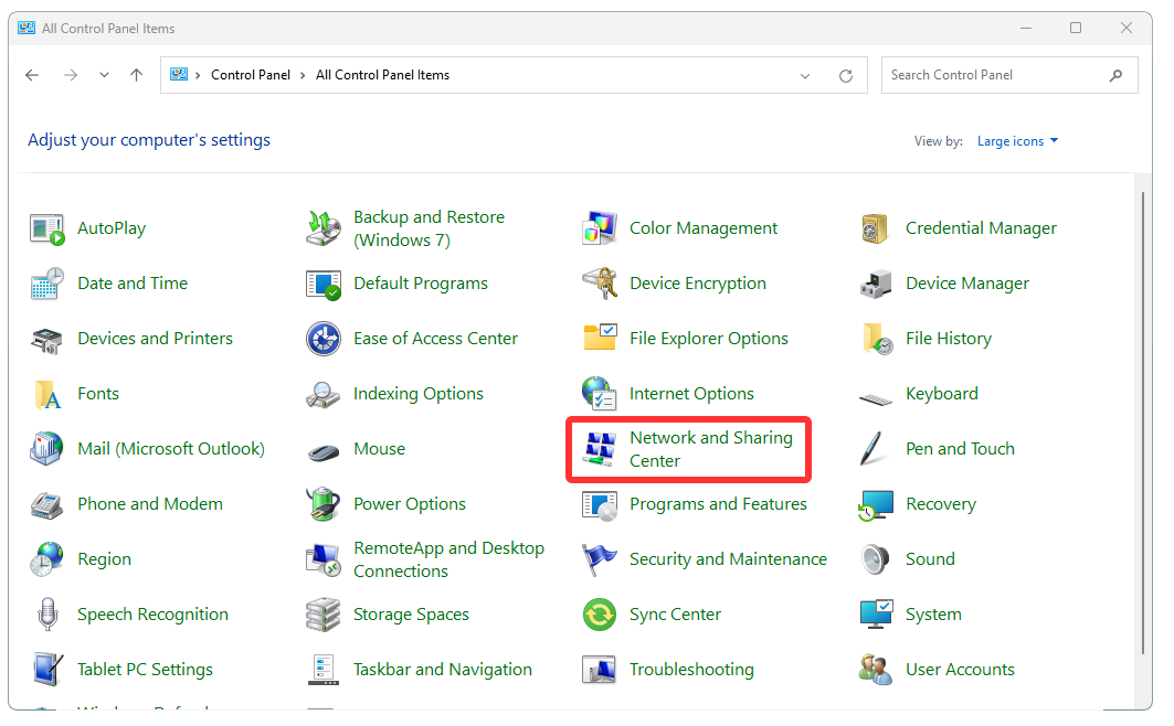
Run Windows Control Panel.
Click on Network and Sharing Center.
If you don’t see Network and Sharing Center in Windows Control Panel, it is because Control Panel is in the Category View mode. In that case, first click on Network and Internet, then click on Network and Sharing Center.
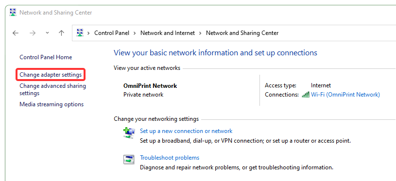
Select Change adapter settings
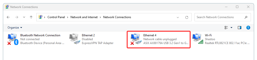
Double-click on the Ethernet adapter to be used (or right-click on the adapter and select Properties).
Your Ethernet adapter may have a different description than the Ethernet 4 pictured above. Don’t be concerned if there is a red ‘x’ on the adapter, which simply means that it isn’t currently connected to anything.
The ExpressVPN TAP Adapter does not represent a physical (actual) Ethernet hardware port and is not usable. This is strictly a “virtual” adapter built into Windows for creating VPN connections and has no purpose for the OmniDTF.
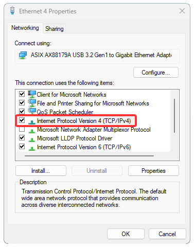
Double-click on Internet Protocol Version 4 (TCP/IPv4) (or single-click on it and then click the Properties button).
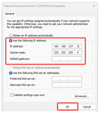
Click the Use the following IP address radio-button (if it isn’t already selected) and enter the following, then click ‘OK‘. IP address: 192.168.127.12 Subnet mask: 255.255.255.0
The Windows Control Panel Ethernet configuration is now complete!
Print Pro
Also, Print Pro needs to know the IP address to use for its communication with the printer. Follow the steps in the below video or the following written instructions to set that up.
Run the Print Pro program.
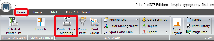
From the Home tab, click on Printer Name Mapping.
Double-click on the first cell space under the Physical Printer Port heading.
Click on the drop-down lists’s down-carat symbol (downward pointing triangle) at the right end of the cell/box.
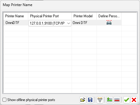
Select “127.0.0.1,9100 (TCP/IP ,RAW)”.
Double-click on the first cell space under the Printer Model heading.
Click on the drop-down list’s down-carat symbol.
Select “Omni DTF” or “Omni DTF Mini”, depending on your equipment.
Double-click on the first cell space under the Printer Name heading.
Type any preferred name for the printer, such as “DTF” or “Mini”.
Confirm that your settings look like the image below (depending on your printer model and Printer Name choice), then click on the green checkmark icon to save the settings.
The Print Pro Ethernet configuration is now complete!
Print Pro provides a rich set of features to set up a print job using one or more images to automate the creation of “gang run” layouts, making the most efficient use of your film effortless. This article is intended to supplement your Omniprint training as a handy reference to refresh your memory and to use as an annotated checklist of the process steps.
View the below videos or see the following instructions for all the basics of loading & configuring images, then creating and positioning the images onto a Layout.
Loading Images
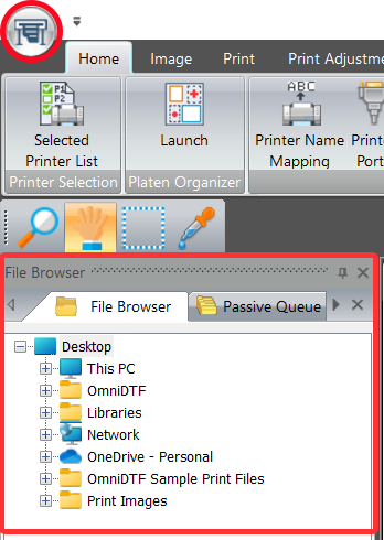
Loading your images is the first step in creating a print job. You can either use the Print Pro ‘File Browser’ or click on the Print Pro printer icon in the top-left corner of the program’s window and select ‘Open…’ to navigate through the Windows file system and select image files to load.
The latter option is recommended because it lets you make your selection from thumbnails of images, rather than just their filenames.
Whether you’re printing a single design or multiple different images for a print job, you’ll want to load and configure each image individually.
Setting the Image Configuration
As each image is loaded, set the following parameters using the Q Rip tool.
If the Q Rip tool isn’t visible go to the Home menu tab, click the Panels item, then select QRip from the drop-down list.
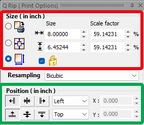
Size the Image
Size the image in the Q Rip window, using the 3rd (bottom) option to rescale the image if needed, ensuring that the width does not exceed 14.25″ for the OmniDTF or 12.5″ for the Omni DTF Mini.
When resizing, be sure the padlock icon option is checked to lock the aspect ratio and prevent distorting the image (see red box in the image).
Position the Image
The default settings of ‘Left’ and ‘Top’ are always used in the Q Rip tool (see green box in the above image.) Changing this setting has no effect on where the image will be positioned on the layout. This is because Print Pro will find the earliest (topmost) point in the layout where each image can fit as they are being added to the print job, maximizing the efficiency of linear film use.
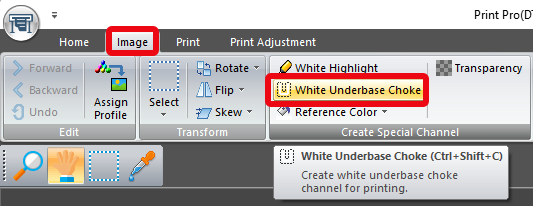
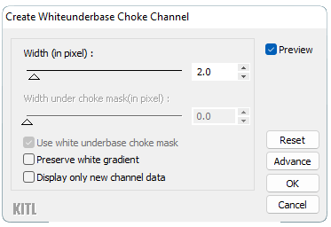
Create a White Underbase Choke
After configuring the image in Q Rip, click on the Image menu tab and then on the White Underbase Choke tool.
Click the ‘OK’ button to accept the default Choke Width value of 2.0.
The image is now configured and ready to be loaded onto a Layout.
If you want to print a Layout with a combination of various images on it, repeat the above steps to open a file, set image parameters, and create a white underbase choke for each image before proceeding.
Creating and Configuring a Layout
Now that any images that we want to print have been loaded and their parameters have been set, we’re ready to create the Layout that the images will be placed onto, using the following steps.
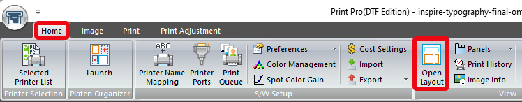
If the Page Layout window isn’t already open, select Open Layout from the Home toolbar
Create a New Layout
Whenever we create a new layout we must also tell the Print Pro software which Environment we want to use for printing the new layout. These Environments are a collection of “presets” that OmniPrint provides to simplify and streamline configuring print jobs.
See the Print Pro DTF Environments knowledge base article for more details about the recommended Environment selection for different situations.
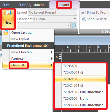
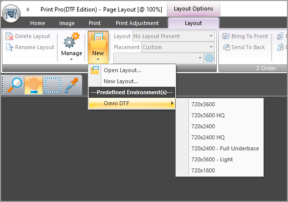
Click on the Layout menu, then select New, then hover over Omni DTF and select the desired Environment from the list that appears.
The Layout window is then loaded and preconfigured with the parameters of the selected Environment.
Put Opened Image(s) onto the Layout
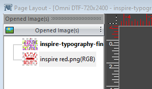
Images opened and configured using the above steps will appear as thumbnails with their filenames under the Page Layout window’s Opened Image(s) header.
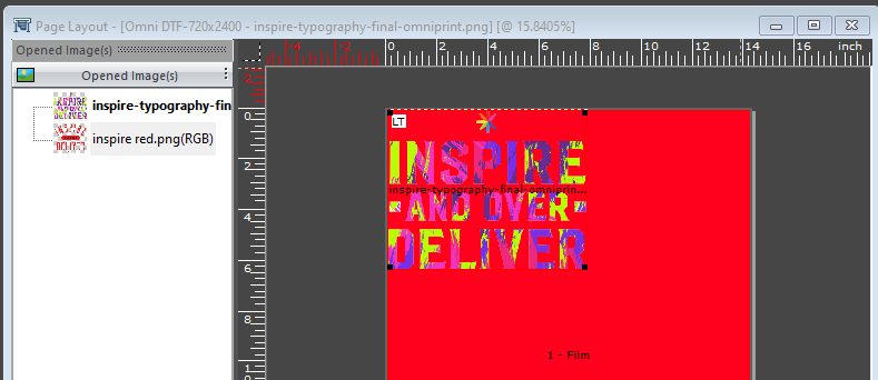
Double-click on any item in the Opened Image(s) list to add it to the Layout.
You can repeat the above step any time to load more images from the Opened Image(s) list onto the layout, or to load more copies of a single image. But there’s a better way to load many copies of an image once it is on the layout.
Duplicating Images on a Layout
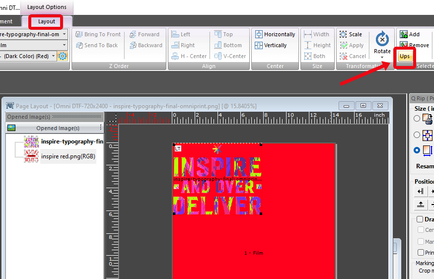
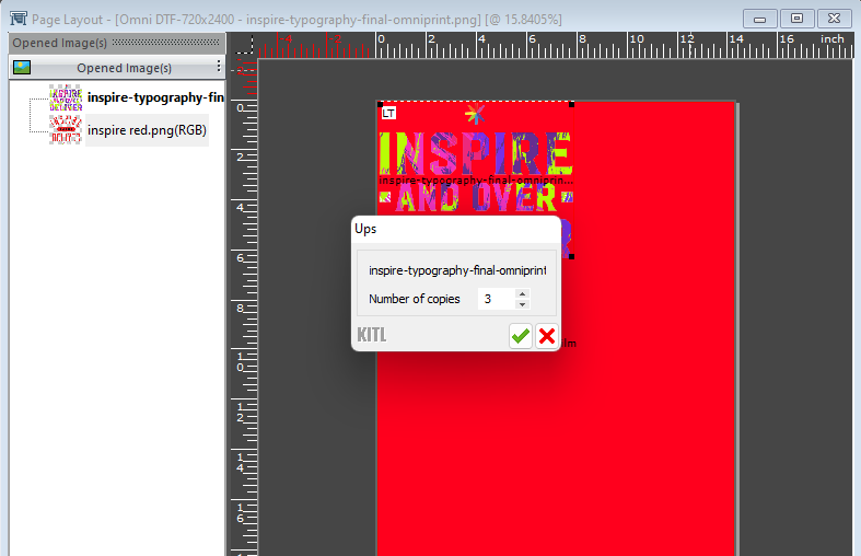
Once an image is on the Layout, you can create additional copies of that image on the layout by clicking the Ups option in the toolbar…
…then enter the number of additional copies you want to add to the Layout into the dialog box that pops up and click the green checkmark.
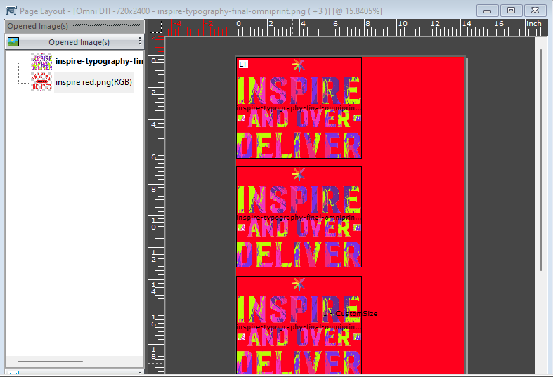
The additional copies of the image will now appear on the Layout. Note: You can scroll down in the Layout window if you want to confirm the number of copies if they don’t all fit in the window’s view. You can also zoom out and in on the layout by using Ctrl+’-‘ (to zoom out) and Ctrl+’=’ (to zoom in).
The ‘Ups’ feature for creating duplicate copies of any image on the layout defaults to copying the image most recently added to the layout. If you want to make copies of a different image (that is already on the layout), first hold down the Ctrl key and click on that image anywhere that it appears on the layout to select that image. Then click the ‘Ups’ button.
That’s how to load images, set their properties, select an Environment for and create a new layout, and place the images onto the layout in Print Pro!
Printing a Layout
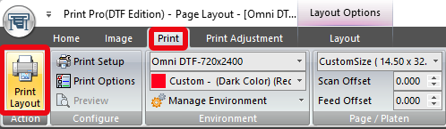
To print the Layout, click the Print menu item, then select Print Layout from the toolbar, or just press Ctrl+’p’….
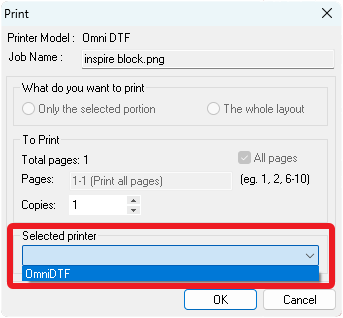
…and make sure your printer is selected in the Print dialog before clicking the ‘OK’ button.
Print Pro DTF Environments are collections of preset options used to select the printing resolution and other parameters when setting up a print job for the OmniDTF or Omni DTF Mini.
Installed Environments are found in Print Pro DTF by selecting the Layout tab, then clicking on New and hovering over Omni DTF or Omni DTF Mini.
To update the Environments in Print Pro for your DTF printer, download the file for your model at the bottom of this article and follow the instructions in the below video or the following written steps. The process is identical for the OmniDTF and the Omni DTF Mini.
Video Demonstration
Installing the Environments
The installation process of the Environments is quick and easy.
Download the Environments file to the PC on which you’ve installed Print Pro.
See the download links at the bottom of this article.
Unzip the contents of the downloaded .zip file (a single .kiee file).
Placing the downloaded file on the Windows Desktop is recommended to easily find the file. It can be deleted after this installation process.
Run Print Pro.
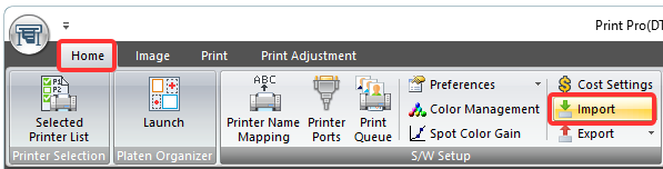
Select the Home tab, then click the Import button.
Select the .kiee file that was downloaded, then click the Open button.
If prompted with a message of “Already ‘Omni DTF-720×3600’ environment exist.” (The actual environment name will vary), click the Yes button.
If prompted to Select environment settings to use, select ‘Use new environment settings only’ and click OK.
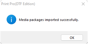
Click OK on the “Media packages imported successfully” window.
Exit out of the Print Pro program, then restart it.
The OmniDTF or Omni DTF Mini Environments have now been updated and are ready for use.
Properly shutting down your OmniDTF printer is very important to ensure that it will be ready to print the next time you start it up. Fortunately, the process is very easy!
Take about 10 minutes to go through these simple steps when you’re finished with your print jobs.
Wet capping the printheads after completing the shutdown maintenance steps is critical to prevent ink from drying in the printhead nozzles, potentially clogging them permanently.
Click the Related Articles link at the bottom of this page if you are experiencing a power outage, printer hardware issue, or PC connectivity problem preventing you from following the instructions below.
Curing Oven Shutdown
If you haven’t already done so, start by turning off the Curing Oven’s main power switch. This is a master switch that will cut power to the Duster, Shaker, and Oven — so shutting off any other switches is optional.
Printer Shutdown Maintenance & Wet Capping
See the below video demonstrating the OmniDTF printer shutdown maintenance and wet capping processes, or read the following description.
Demonstration video
Please also see the Prepare for Success section below after viewing the video for tips on minimizing your startup time and keeping your white ink in top shape.
Step-by-step instructions
Press and hold the Carriage Left button until the printhead carriage is in the center of its range of motion to ease access to the ink clips and expose the capping stations and wiper blade.
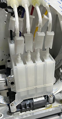
Clamp all 8 of the ink line clips shut.
Use the Carriage Left button again to move the printhead carriage to its full-left position.
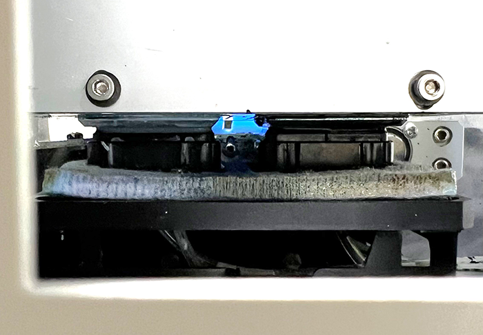
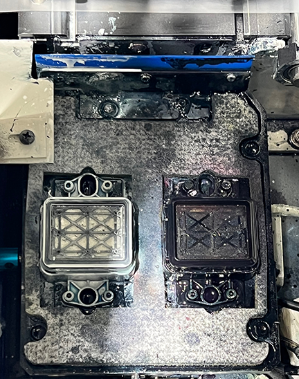
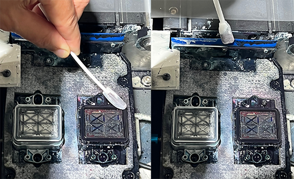
Wet an anti-static foam swab or a clean, lint-free cloth with Super Cleaner to thoroughly clean:
The full length of the wiper blade
The rubber seals surrounding both capping stations
Remove any bits of dried ink on the capping station sponges or seals with tweezers.
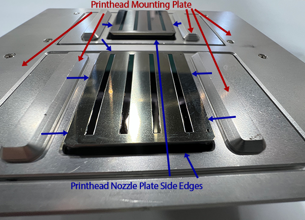
The remainder of the steps before wet capping the printhead are all about keeping the printhead mounting plate and the side edges of the printhead nozzle plates clean. If these areas are allowed to accumulate ink then eventually the dried ink will hang down below the printhead and leave streaks on the film.
Before continuing this maintenance process, please note the following images of the shape and relationship of these parts to each other, and examples of how they may appear before and after cleaning.
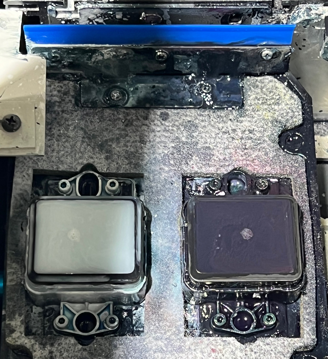
Area of printhead mounting plate and nozzle plate edges to be cleaned. Bottom of printhead mounting plate with printheads installed. Red arrows point to areas of the mounting plate; blue arrows point to the nozzle plate side edges
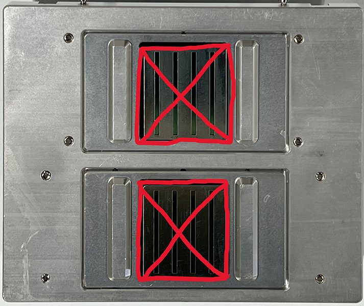
Areas of the printhead nozzle plate cleaned by the wiper blade, not manually Red X’s mark the face of the nozzle plates, an area that we don’t clean manually.
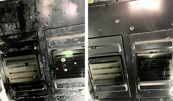
Before & After examples of dirty and clean mounting plates and nozzle plate edges Cleaning the mounting plate and nozzle plate edges daily prevents ink buildup.
Now that you’re familiar with the area we’ll be working with, let’s proceed with cleaning the mounting plate and the side edges of the printhead nozzle plate.
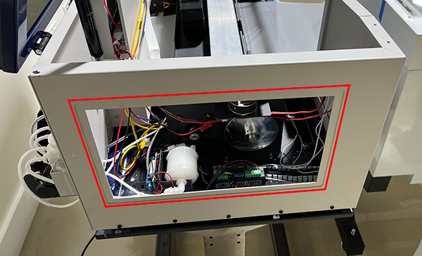
Remove the left-side window to access the chassis interior’s left side. Left side of OmniDTF printer with the window panel removed.
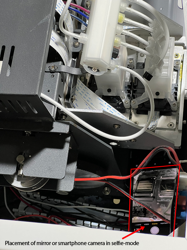
Place a mirror or smartphone camera in selfie-mode inside the front-left corner of the printer chassis, tilted at an angle to provide you with a view of the printhead plates and their mounting plate, which face downward on the bottom of the printhead carriage, to orient yourself and get your hand into position to begin cleaning the area.
Top-down view of a smartphone in selfie-mode tilted at an angle to display the printhead mounting plate and the printhead nozzle plates.
Use a clean, lint-free cloth dampened with Super Cleaner to reach under the printhead carriage and wipe any ink from the mounting plate and the side edges (only) of the printhead nozzle plates.
A foam swab can be used to clean the area at the front of the white ink printhead if a cleaning cloth wrapped around a finger won’t fit in the space.
If contact with the printhead’s nozzle plate is made accidentally, dab the contacted area with Super Cleaner on a clean, lint-free cloth before wet capping.
Wet Capping the Printhead
Fill both capping stations to the brim with Super Cleaner.
The wiper blade and capping station seals should now be free of any ink build-up and the capping station sponges completely submerged in Super Cleaner, up to the top of their seals.
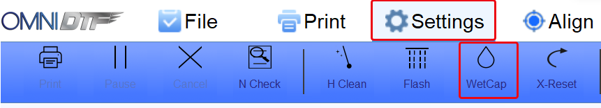
Click the WetCap button under the Settings tab in the OmniDTF Windows program.
This will send the printhead carriage to its docked position and raise the capping station seals to press against the bottom of the printhead plate, bathing it in Super Cleaner within an air-tight seal.
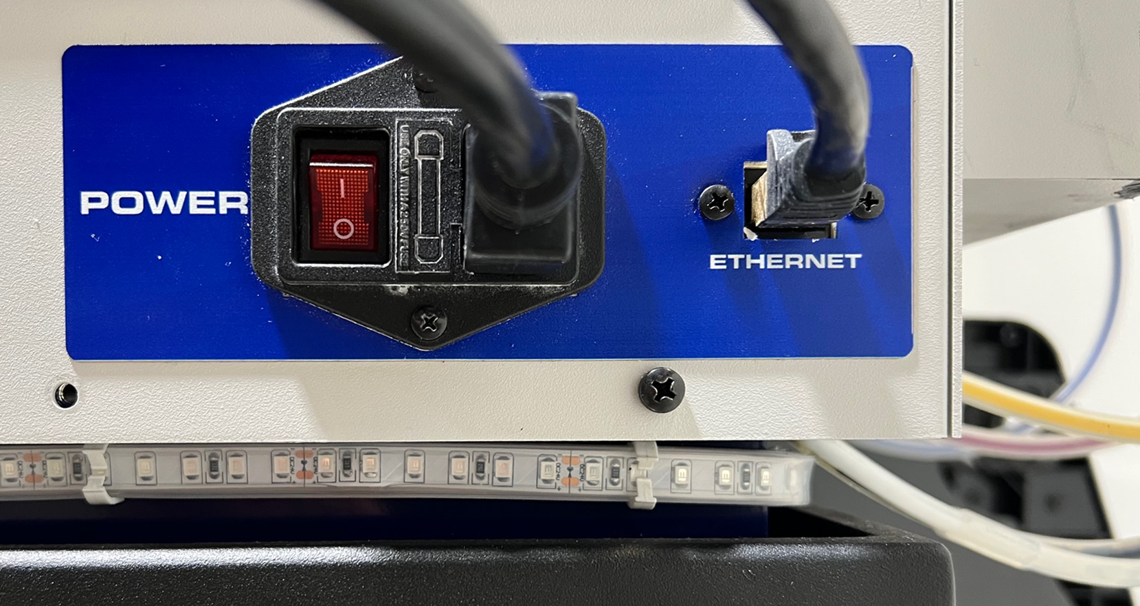
The printer can now be turned off from the power switch on the right side, near the back of the printer.
The printhead maintenance components have now been cleaned and the printhead is wet capped.
Prepare for Success
We recommend two more steps to wrap up your shutdown process by preparing your printer in advance for the next day of printing.
Empty the waste ink bottle for a fresh start next time the printer is used.
Agitate the white ink to mix any separating pigment and prevent sediment from collecting in the bottom of the white ink bottles.
Press a clean cloth or finger against the ink bottles’ breather hole to avoid spillage.
Shake the bottle aggressively for 15-30 seconds to thoroughly mix the ink.
When finished, use a clean cloth to wipe away any ink that appears to be blocking the breathing holes in the center of the bottle caps.
We can also shake the white ink during the startup process, and will want to do that if the printer has been idle for several days. However, shaking the white ink will result in small bubbles forming so we need to wait at least 15-30 minutes after shaking before circulating the white ink or printing.
If using the OmniDTF nearly every day, shaking the white ink at the end of a printing day, rather than at the beginning, helps to keep the pigment mixed while not delaying the startup process next time we want to use the printer.
That’s all there is to it. Your printer is now well-maintained and ready for your next day of printing.
The daily startup routine for the OmniDTF system is very straightforward and can be made even simpler by following a few tips that we’ll include in this brief overview of the process.
Preliminary Steps
Before starting up the printer, first start up the OmniDTF UI program on your PC, in order to automatically load configuration data when the printer is turned on.
Note that the connection icon in the lower-left corner of the window will flash red until the printer is turned on.
Also, empty the waste ink bottle at the right-rear corner of the printer (left if viewing from the back) if it contains any ink before turning on the printer.
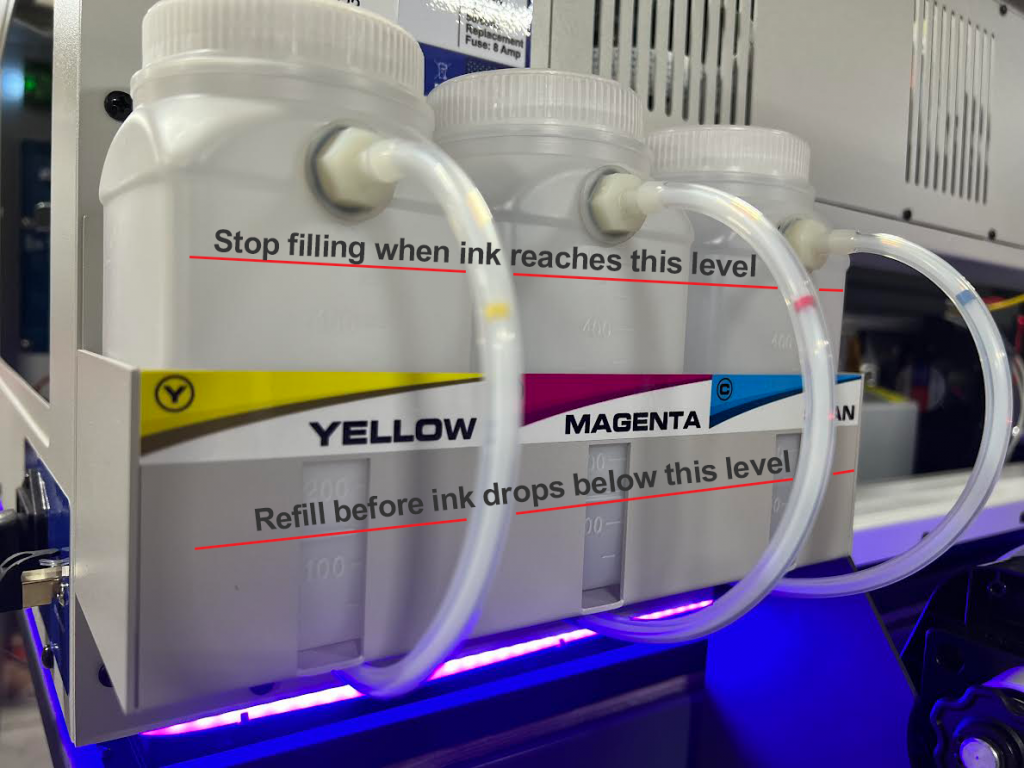
Always check your ink levels before printing and fill the bottles to the level shown above. Be careful not to overfill the bottles because if the ink level reaches the bottle’s fitting where the ink tube enters the bottle as this can cause leakage.
It’s important to never let the ink level in the bottles get below the refill level shown above to maintain good ink flow and avoid getting air into the ink lines.
If the printer has been idle for longer than two days or if the white ink is not opaque, shake the white ink bottles vigorously (while covering the holes in their lids) for 15-20 seconds. Then wait for at least 15 to 30 minutes to allow the white ink to settle before starting up the printer and running the routine white ink circulation.
When finished, use a clean cloth to wipe away any ink that appears to be blocking the breathing holes in the center of the bottle caps.
The final step before turning on the printer is to confirm that the white ink lines are clipped shut. This should already be shut since that is an important step of the shutdown procedure, but it’s advisable to double-check now.
Starting up the OmniDTF printer
Start-up video demonstration
Step-by-step instructions
Turn on the printer using the power switch on the right side, near the back.
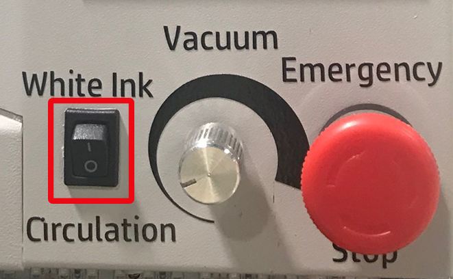
Circulate the white ink by turning on the White Ink Circulation switch on the front of the printer if it isn’t already on. You will hear it running for 3 minutes when switched on, and will then automatically turn off.
Confirm that the rotary Vacuum switch, shown above, is on (not fully counter-clockwise.) It’s recommended to keep this at its minimum strength, which provides plenty of vacuum power to keep the film against the platen without cooling the platen heaters.
The White Ink Circulation and Vacuum switches can be left in their ON positions at all times. Then they will automatically engage when the printer is turned on.
After the white ink circulation pump has stopped running, open all eight of the ink clips
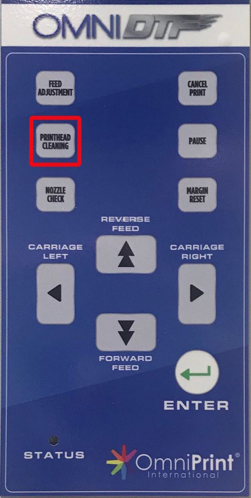
Press the Printhead Cleaning button on the printer’s control pad to run a head clean.
Once the control pad display indicates that the head clean is finished, press the Printhead Cleaning button once more to run a second head clean.
Press the Nozzle Check button on the printer’s control pad to print a nozzle check test pattern.
If the nozzle check isn’t at least 90% complete on all 8 channels, additional Printhead Cleaning should be done to achieve that standard.
Be careful to keep an eye on the fluid level in the waste ink bottle if running multiple head cleans, and be sure to empty it before it gets beyond 2/3 full.
Confirm that there is an appropriate amount of DTF Powder at the bottom of the U-shaped loop of film in the dusting chamber and add more as needed.
Turn on the curing oven assembly’s main Power switch, along with the Curing switch to begin heating the oven.
The previous oven settings will be retained so typically won’t need to be adjusted as part of the daily startup process.
If the film in the oven is being heated excessively and warping, keep the film moving through the oven by continuing to print, or lift the oven’s lid open when the printer is idle.
The printer is now ready and you can proceed with production work!
Production Notes
Monitor the status of the following items periodically when printing to ensure trouble-free operation and optimal print quality:
Film Alignment: Confirm that the film runs straight through the printer, across the bridge, and through the oven assembly. Center it with the yellow stickers’ alignment lines and at the opening to the Dust-Curing Machine where the bridge rests. Pause printing and adjust as needed to correct any skewing.
Powder dusting: Activate as needed to maintain sufficient powder on the film.
Powder shaking: Adjust as needed to effectively remove excess powder.
Waste ink bottle: Monitor the level before running a head clean and empty the bottle before it exceeds 2/3 full.
Ink bottles: Refill before the level drops to 1/2 full to maintain optimal ink flow and prevent air from entering the ink lines.
Powder: If the powder dispenser supply is depleted, briefly pause printing and refill the supply.