The i2 UI (user interface) software is used to control, adjust, and maintain the system, as well as to send ripped print jobs to the OmniPrint i2 printer.
The below video and the following step-by-step instructions demonstrate the easy & quick process of installing the software, and one small configuration setup that we make once it’s installed.
Demonstration Video
Step-by-Step Instructions
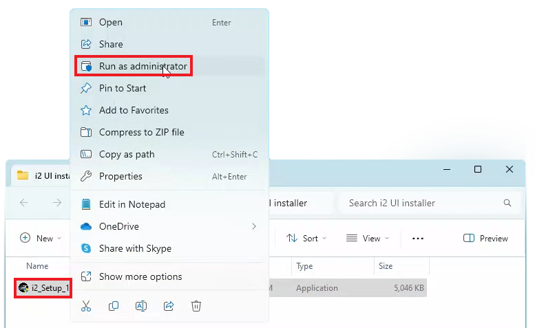
Right-click on the setup program on your i2 UI software’s USB thumbdrive, then select Run as administrator.
The current filename as of the creation of this article is i2_Setup_1.9.0 but you may have a different version number.
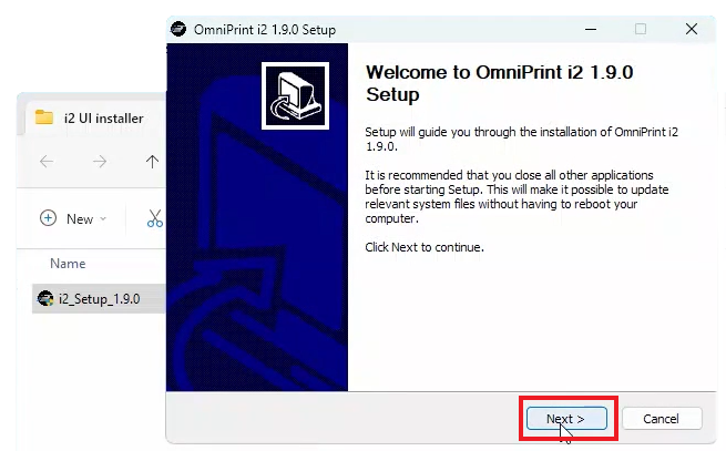
Click the Next > button on the welcome screen.
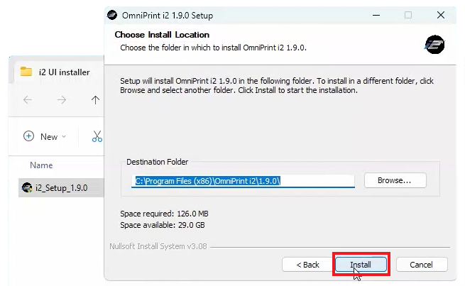
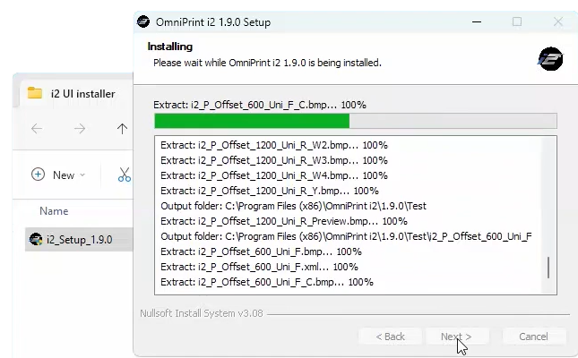
Accept the default Destination Folder for the installation, or select your preferred folder, then click Install. The setup program installs the i2 UI program to the PC, providing constant status details.
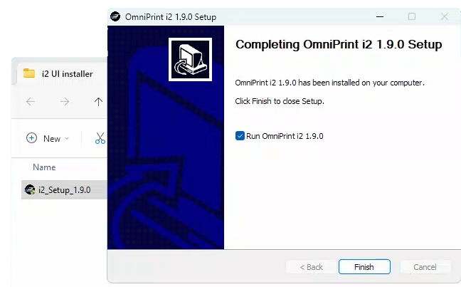
Upon completion of the installation, an icon for launching the i2 UI software appears on the Windows Desktop and the Setup program presents a Finish button to quit the installation and load the i2 UI program
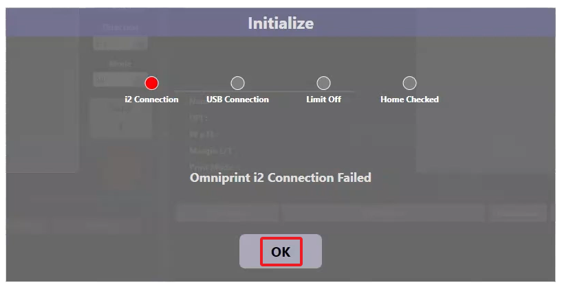
Click the Finish button to run the i2 UI program. The i2 UI software loads and connection testing begins.
We haven’t yet connected the PC that we’ve installed the i2 UI software onto, so the i2 Connection test will fail. This is expected and is not a problem for the purposes of continuing with the configuration process.
Click OK on the Initialize window.
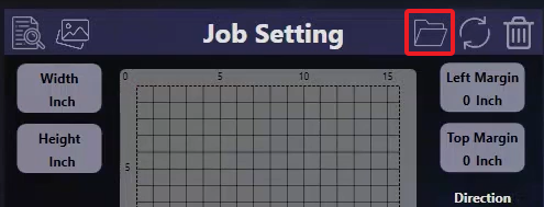
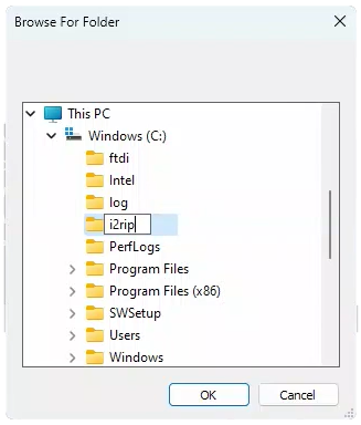
Click on the folder icon at the top of the Job Setting section. A Browse For Folder window appears. This is where we tell the i2 UI software where to find ripped files to load and print.
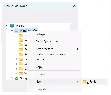
Any file system location available to Windows can be used. We recommend using your drive with the best combination of speed and capacity. For our example, we create a new folder named “i2rip” at ‘C:\’ (the root level of the PC’s primary storage location).
To use our recommended location, right-click on ‘C:’, hover over New, then click on Folder when the option appears. A new folder with the name of ‘New folder’ appears.
Enter ‘i2rip’ or your preferred name to be used in place of ‘New folder’, then click the OK button.
The i2 UI software installation and configuration is now complete!
The OmniPrint i2 comes with two software tools: Print Pro RIP software and the i2 UI program.
The below video and following step-by-step directions demonstrate and explain the workflow of using Print Pro to configure & rip a print job to a file, and the i2 UI to precisely position the print on the platen, select print modes, and send the print job to the printer.
Video Demonstration
Step-by-Step Directions
We’ll split the process into two sections: 1) ripping an image to a “print” file, and 2) printing the image. The first section uses the Print Pro software while the second section uses the i2 UI software.
Let’s get started!
“Printing” an Image RIP to a File
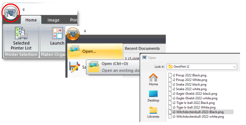
Load an image file to be printed into Print Pro.
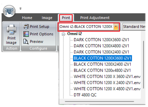
Select an Environment (based on shirt color & desired resolution) from dropdown list on the Print tab’s toolbar to load presets.
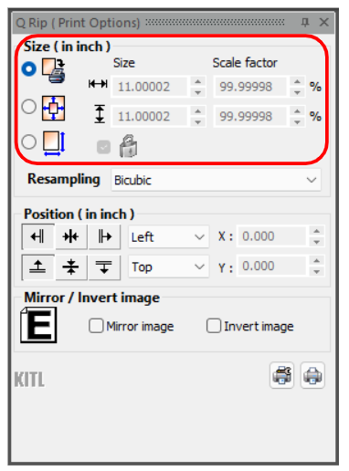
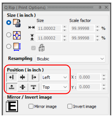
Set the desired image size for the print in the Q Rip panel.
Position the image at top-left in the Q Rip panel (actual positioning is done later).
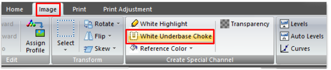
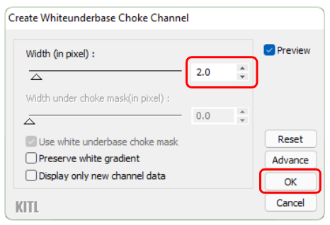
Select White Underbase Choke from the Image tab’s toolbar… …then accept the default of 2 pixels and click OK to create the choke.
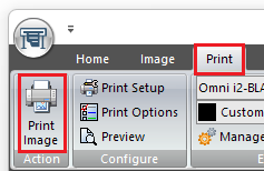
Click Print Image on the Print tab’s toolbar.
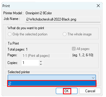
Click the Selected printer dropdown and select the i2, then click OK.
The ripped image has completed its print-to-file process when the Status in the Queue Manager says “PrintDone”, so we will now switch to the i2 UI software to continue.
Finalizing and Sending the Job to the i2
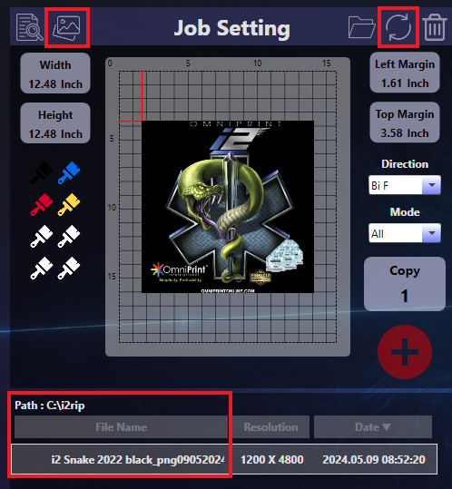
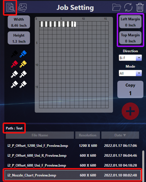
Confirm that the “i2rip” folder is selected in the i2’s Job Setting section (by clicking on the ‘photos’ icon) and that the file list in Job Setting is current (by clicking on the ‘reload’ icon), then select the ripped file name to be printed.
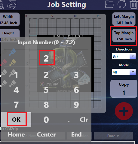
Set the top margin to 2 inches.
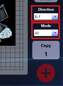
Set Direction to “Bi F”.
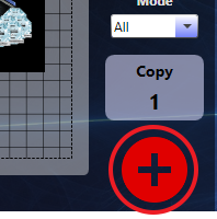
Set Mode to “All”. NOTE: See the above video for details on the Direction and Mode options.
Click the red ‘+’ button to send the job to the Print Status queue.
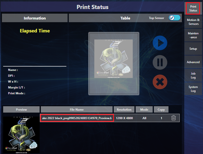
Go to the Print Status tab (if not already there), then click the image’s file name in the Print Status queue. A thumbnail of the image to be printed appears in the print queue Preview section and on the Print Status platen representation.
Mount a pretreated garment onto the platen.
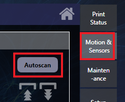
Go to the Motion & Sensors tab and click the Autoscan button to set the platen height.
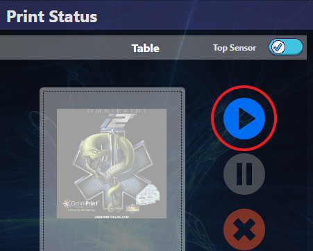
When the Autoscan is completed, go back to the Print Status tab and click the blue “play” button.
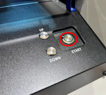
When the i2 printer’s Start button flashes, push it to run the print.
That completes the process of ripping and printing a graphic.
You can keep the ripped image file sets in the C:\i2rip folder (or wherever your software is configured to store them) for future printing, which allows you to skip the ripping process next time you want to print the exact same image.
The Print Pro software is included with the OmniPrint i2 printer package, providing a robust set of tools to “rip” your images for DTG and DTF printing.
Print Pro can be installed onto any number of Windows PCs, but can only be used on one PC at a time.
Use the following instructions to reinstall the software or to install it onto another PC, and to configure it for use with the OmniPrint i2.
Installation Video
Installation Steps
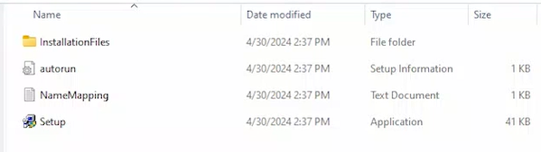
Insert the Print Pro USB thumb drive into a USB port on your Windows PC, then open Windows File Explorer and navigate to the thumb drive.
You may alternately copy the contents of the thumb drive to the PC and direct File Explorer to that location.
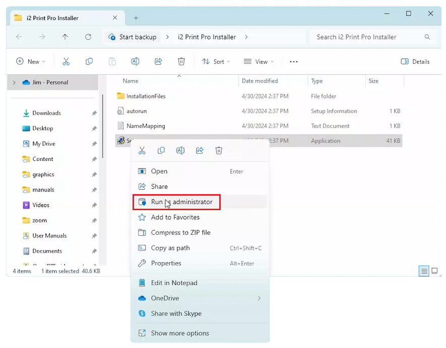
Right-click on the Setup program, then select Run as administrator.
Click Next at the first two prompts.
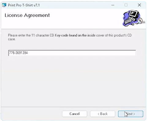
Select I Agree on the License Agreement screen to continue the installation, then click Next.
When prompted to enter the CD Key code, type the following (including the hyphen), then click Next: 776-3691394
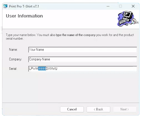
Enter any information you like into the Name and Company fields, followed by the Print Pro software’s serial number, as shown on the plastic case that the software’s USB thumb drive and security key (“dongle”) devices came in. The serial number will be in the following format: LPWM####DXVWU where the “####” is replaced with 4-numbers, which are also found on the thumb drive and dongle.
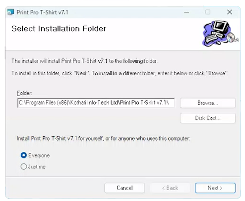
Accept the default installation on the next screen. You may also accept the default setting of “Just me” or “Everyone” on the same screen.
Your selection will depend on whether you want to restrict access to Print Pro to only users logged in to Windows using the current login credentials in use or to make Print Pro available to anyone using the PC with any login credentials. Click Next when ready to proceed with the installation, then click Next again on the following screen.
Click Close on the Installation Complete screen.
When prompted to install the HASP Driver, click Yes. This prompt may have appeared behind other program’s windows on the Windows Desktop, so if you don’t see it then minimize any running programs until the HASP Driver installation prompt appears.
When the HASP Driver installation is finished, Print Pro is fully installed.
Continue with the quick & easy Print Pro configuration process detailed below to prepare it for use with your OmniPrint i2 printer.
Configuration Video
Recommended Configuration Steps
The following steps, though not required, are recommended to provide a clear workspace and eliminate visual distractions within Print Pro.
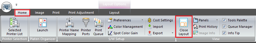
Close the Layout window by going to the Home tab and clicking its toolbar’s Close Layout button.
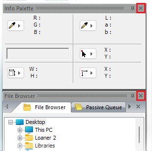
Close the Info Palette and File Browser window panels by clicking on the ‘x’ in their upper-right corners.
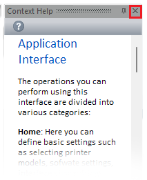
Close the Context Help window panel.
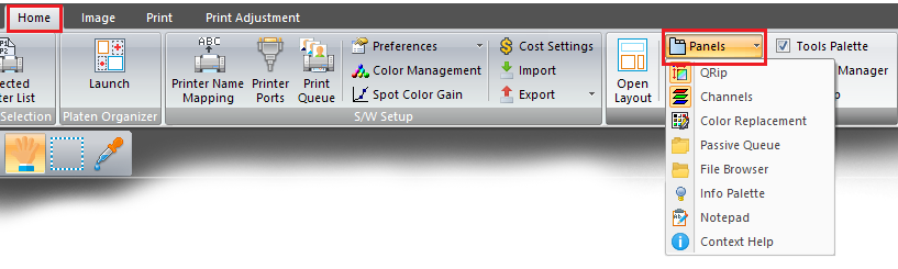
These closed panels (and others) can be displayed again by click on the Home tab’s Panels tool, then selecting any desired item in the dropdown list.
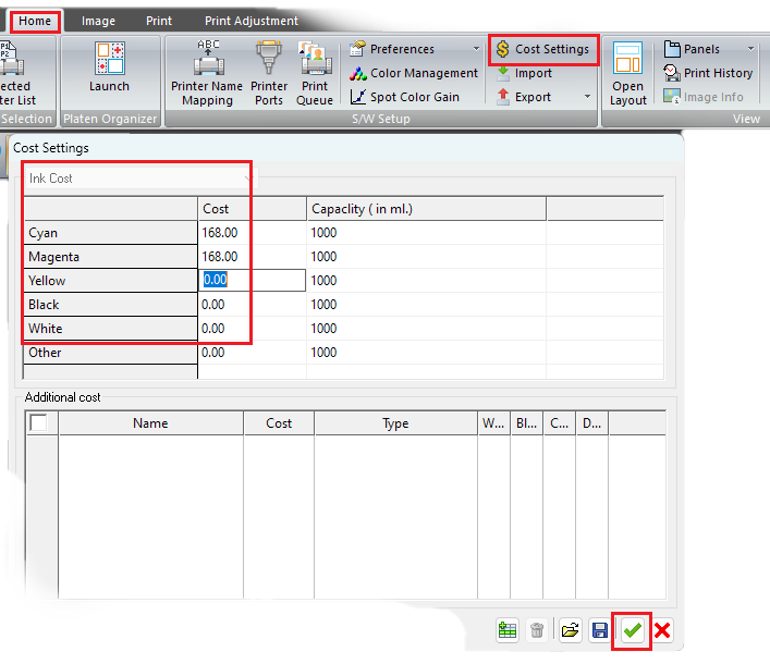
Enter the per liter ink cost so that Print Pro can provide you with the total cost of ink for printing any sized and configured design. – Click Cost Savings on the Home tab tollbar. – Enter the cost for a liter of ink for each color, then click the green checkmark.
Required Configuration Steps
The below steps are required for using Print Pro with the OmniPrint i2. Details of the OmniPrint i2 workflow and the related purpose are explained following the description of the steps, for those interested in that information.
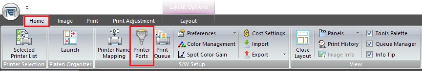
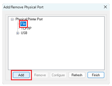
Select Printer Ports on the Home tab tool bar. The Add/Remove Physical Port window appears.
Select File then click the Add button. The Add File Port window appears.
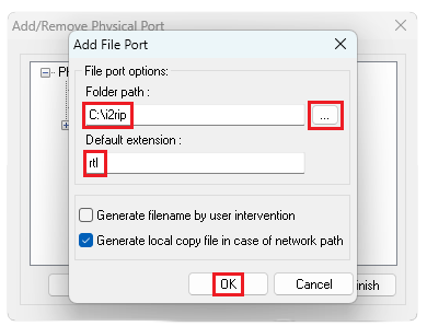
Click the ellipses (“…”) button to the right of the Folder path textbox to select a folder where all rip files will be saved.
You will have an option to create a new folder, such as the recommended “i2rip” folder at “C:\”.
Enter “rtl” in the Default extension textbox, then click the OK button. The Add File Port window closes.
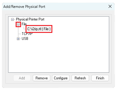
Click the ‘+’ sign to the left of File to confirm that your selected folder and file extension entries were saved, then click the Finish button to close the Add/Remove Physical Port window.
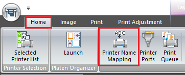
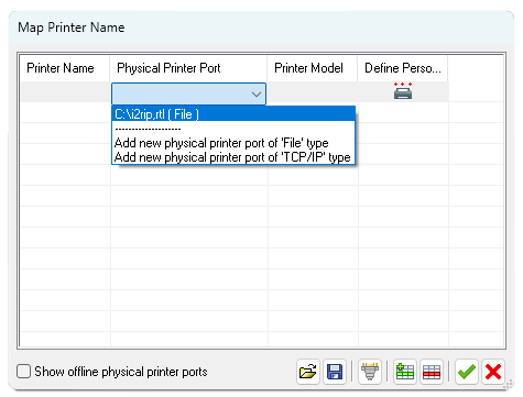
Select Printer Name Mapping on the Home tab’s toolbar. The Map Printer Name window appears.
Double-click on the first row below the Physical Printer Port column heading, then click on the down-caret symbol that appears at the right end of the field and select ‘C:\i2rip,rtl ( File )‘.
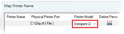
Double-click on the first row below the Printer Model column heading, then click on the down-caret symbol that appears at the right end of the field and select Omniprint i2.
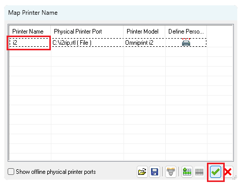
Double-click on the first row below the Printer Name column heading, then enter any name that you’d like for the printer to be known as in Print Pro, then click the green checkmark. For our example we’re simply using “i2”. The Map Printer Name window closes.
The Print Pro configuration process is now complete and Print Pro is ready for use with the OmniPrint i2.
i2 workflow & RIP file placement
The i2 workflow separates the processes of “ripping” images and printing them. In this workflow, first the artwork to be printed is loaded into Print Pro where its desired printing dimensions are sized and printing parameters defined by selecting an Environment (a collection of presets). When Print Pro receives commands to print, it “rips” (processes) the currently loaded image and creates rip files which are saved to the PC’s storage.
Once a rip is completed, the i2 UI software is used to load the rip file, position the image within the dimensions of the printer’s platen, and then send the print job to the printer.
Our required configuration steps in Print Pro are essentially telling the software that it will be sending rips to a file (rather than directly to a printer) and where in the PC’s file system to save rips.
The OmniPrint i2 printer communicates with its controlling PC over both Ethernet and USB 3.0, and requires an enhanced USB driver — the FTDI driver, which is included with the printer.
See the below video or the following step-by-step instructions to reinstall the driver, or to install it onto a new PC.
Video Demonstration
Step-by-Step Instructions
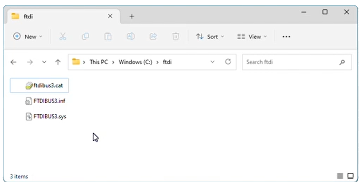
Copy the ftdi folder from the USB thumb drive provided with your printer to your Windows PC, then open the copied folder in Windows File Explorer.
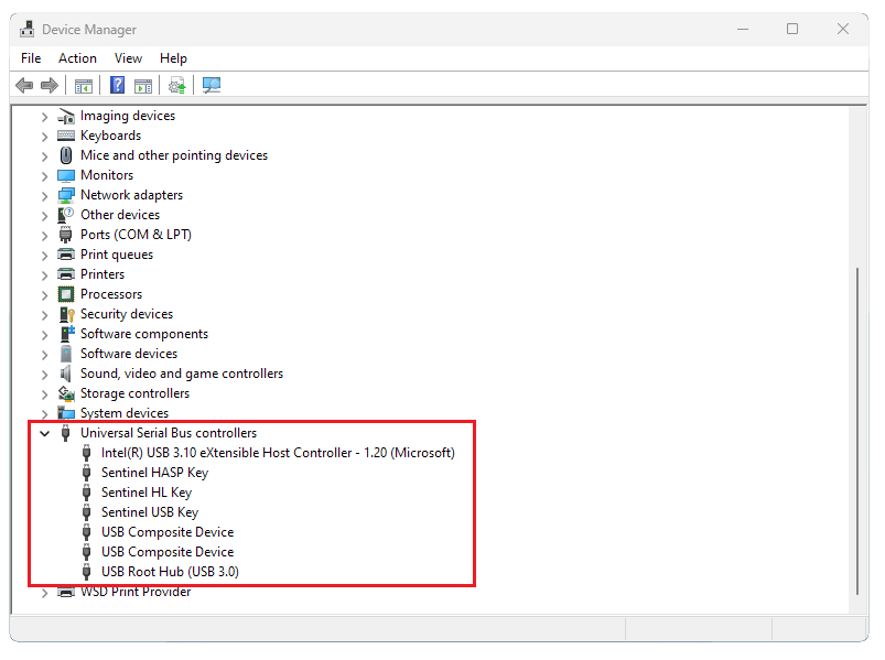
Open Windows’ Device Manager, then expand the Universal Serial Bus controllers section in Device Manager.
Connect your i2 to a USB 3.0 port on your printer using the provided cable, then turn the i2 on.
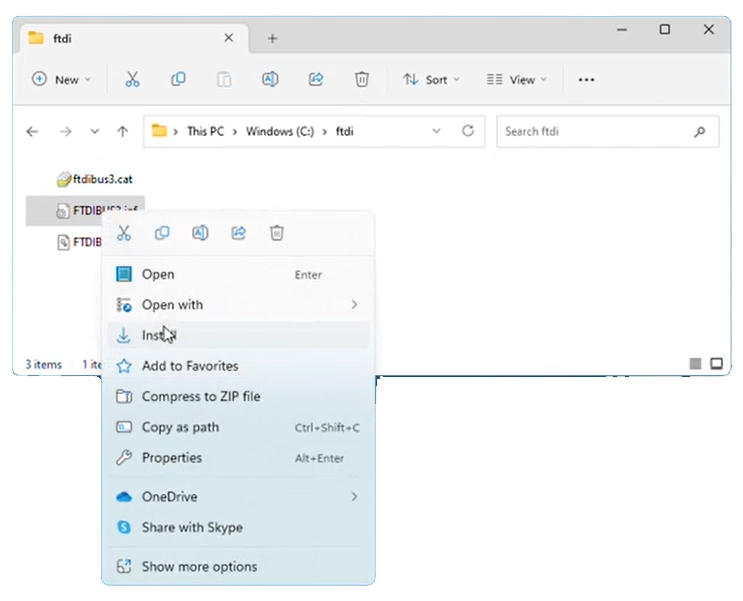
Right click the FTDIBUS3.inf filename in the previously opened folder in File Explorer, then click Install.
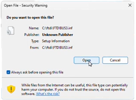
Click Open on the dialog that appears, and proceed when prompted by Windows.
This concludes the installation process.
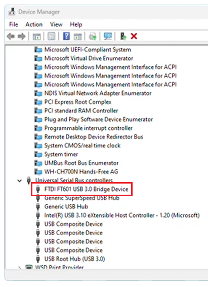
You will now have a new FTDI FT 601 USB 3.0 Bridge Device entry in the Universal Serial Bus controllers section of Device Manager.
Optimal print quality requires that the printheads be a consistent distance from the fabric or film being printed upon. Otherwise, the sections closest to the printhead will have the sharpest detail and the sections furthest from the printhead will have the most overspray and appear more fuzzy.
Platens that aren’t consistently the exact same distance from the nozzle plate also complicate printhead alignments, and may make it virtually impossible to reach the hardware’s potential for very fast & high-quality bi-directional printing.
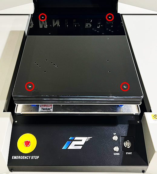
There are four points of measurement and adjustment to ensure an equal distance between the printhead and each corner of the platen. All four are found on the top surface of the platen so readily accessable for adjustment, if needed.
Checking and adjusting the platen-printhead distance is a straightforward process that only takes a few minutes, so let’s get started.
Tools and Supplies
Two coins, or similarly size and stackable objects.
1/8″ Allen wrench/Hex key (if adjustment required).
Checking & “Leveling” the Platen
Let’s preview the process to check & adjust for equal distance across the length and depth of the platen before jumping into the step-by-step details.
We will be moving the carriage away from its home position on the capping station and using the left or right side brackets that the printheads are mounted onto as our upper reference point.
Starting with the carriage near the center of the printer, we’ll systematically check the distance between each of the four platen adjustment screws and work our way around the platen to ensure that all four adjustment points are the same distance from the bottom of the printhead mounting bracket.
Use the printer’s Down button to lower the platen about an inch below its last-used setting.
Manually push the printhead carriage toward the center of its range of motion after closing any open ink clips to prevent or minimize dripping.
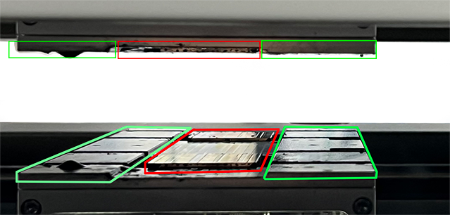
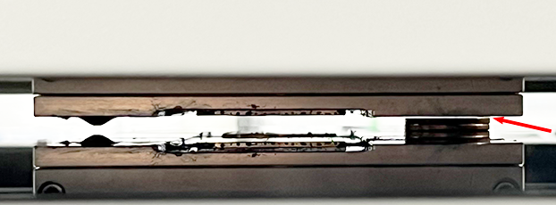
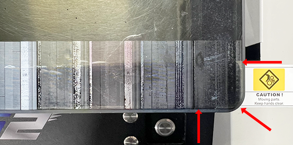
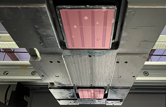
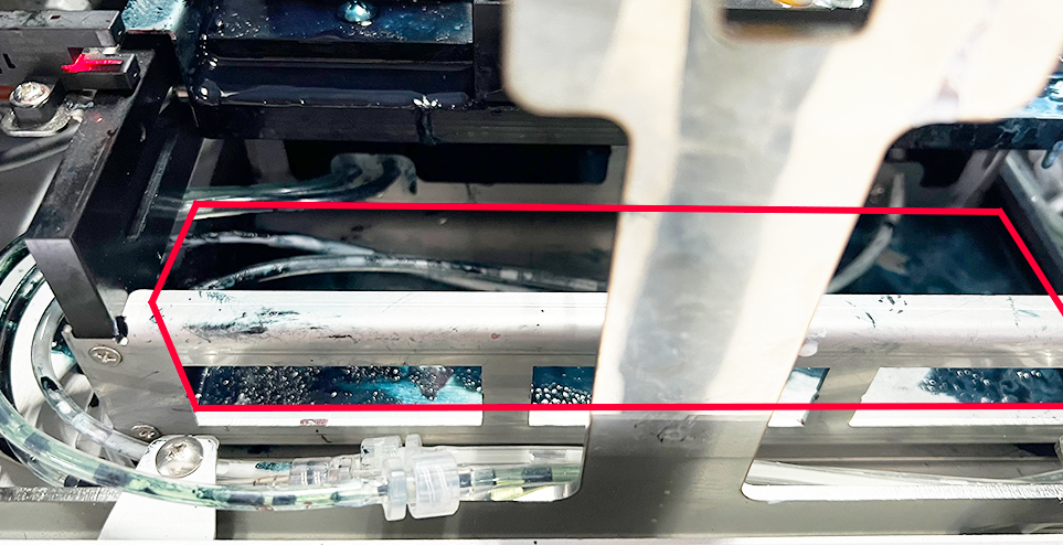
Lower your perspective to look across the top of the platen to get a view of the undercarriage. Then identify the printhead mounting bracket frame and distinguish it from the printheads’ nozzle plates.
In the below photo, the nozzle plates are outlined in red while left & right mounting bracket frame sections are outlined in green. The top section of the photo is a direct side view of the undercarriage while the bottom section is a reflection of the undercarriage on the platen.
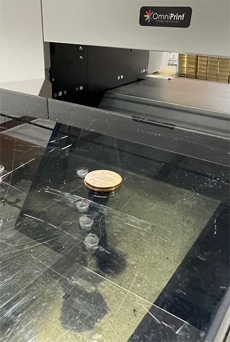
Place two stacked pennies (or similar stackable objects) on the rear right adjustment screw of the platen…
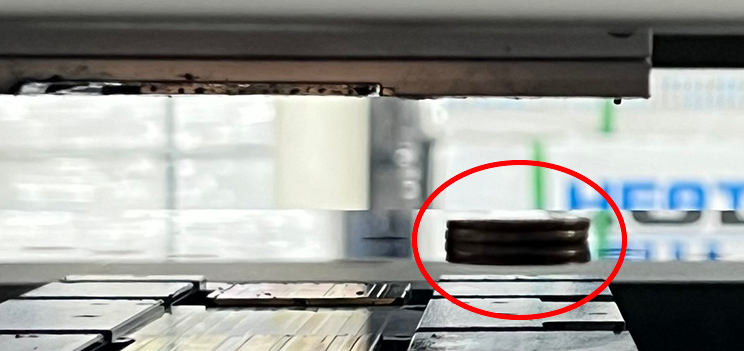
…then manually position the carriage and gantry so that the left or right side of the printhead mounting bracket is directly above the pennies.
Carefully use the printer’s Up button to raise the platen until the top penny almost touches the bottom of the carriage’s printhead mounting bracket.
Slowly move the gantry forward & backward to confirm that the bracket never touches the pennies, adjusting the height very slightly if needed to prevent contact. This will be our starting baseline height.
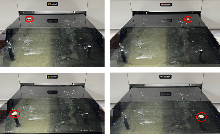
Reposition the pennies to each of the other three adjustment screws, one position at a time. At each position, compare the distance to our baseline height (at set at the first position we checked) and adjust as needed to create the same distance at each position.
To lower an alignment point, turn the adjustment screw clockwise as when tightening a screw, which is exactly what you are doing.
To raise an alignment point, turn the adjustment screw counter-clockwise.
That’s all there is to it.
Aligning the printheads is recommended if adjustments were made. See the below link for instructions, if needed.
Optimal print quality requires that the printheads be properly aligned. Printhead alignment is done during the initial setup process and may be done as a maintenance task at other times if needed.
Preliminary Checks
The following steps should be taken before changing the printhead alignment. Modifying the alignment without first completing these checks may result in misaligning the printheads while unintentionally compensating for a mechanical issue.
Ensure that the printer is level, adjusting the height of the table’s four feet/casters as needed.
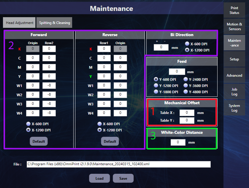
The Head Adjustment tab of the i2 UI program’s Maintenance screen is where adjustments are made, in response to visual feedback from test pattern prints.
The Mechanical Offset is adjusted first to position the starting x,y position (0,0 by default) at the flat front-right corner of the platen — inside the beveled edge.
Forward, Reverse, and Bi-directional (horizontal) alignment must be done at the 1200 DPI setting.
Vertical alignment between the two heads is done using the White-Color Distance control.
Let’s get started!
Mechanical Offset
The Mechanical Offset‘s ‘Table X’ and ‘Table Y’ settings calibrate the top-left corner of print jobs, which may also be thought of as the near right corner of the platen when viewing from the front of the printer.
i2 platens have an approximately 1/8″ bevel around their outside edge. This should not be considered part of the platen’s printable area. We want to confirm that a nozzle check print has its top-left corner (bottom-right from the front of the printer perspective) at the edge of the flat area of the platen. There should be virtually no space between the platen’s flat edges and the ink, and there should be no ink on the beveled part of the platen.
Select the i2_Nozzle_Chart_Preview.bmp file from the Test path in the i2 UI software’s Job Setting section.
Set both the Top & Left Margins of the Job Setting section to ‘0’.
Send the job to the print queue and print it.
If the top-left corner of the nozzle check pattern print isn’t positioned at the corner of the platen (the flat part of the platen, not on the beveled edge) then we’ll need to change the X value (for horizontal adjustments) and/or the Y value (for vertical adjustments).
Increasing the values shifts the print toward the center of the platen. Decreasing the values shifts the print towards the edges of the platen.
If adjustments are needed, click the Save button after changing any values and before running another test print. Repeat as needed to position the corner of the print at the corner of the platen.
Horizontal Alignment
There are three horizontal alignments: Forward, Reverse, and Bi-Directional. These names describe carriage movement when printing occurs — when the carriage is moving in the forward direction only, in the reverse direction only, or in both directions. Most printing is done bi-directionally for the speed benefit, but alignments for all three types of printing must be performed.
Carriage Forward movement as defined as right-to-left when facing the front of the printer, which is left-to-right from the perspective of the printed image.
The process for checking and adjusting the Forward & Reverse alignments are identical so we’ll provide step-by-step details for the Forward alignment, and only list the differences for the Reverse alignment.
Forward horizontal alignment
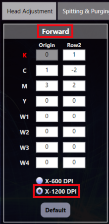
Select the ‘X-1200 DPI’ setting at the bottom of the Forward section on the Head Adjustment tab of the i2 UI software’s Maintenance screen.
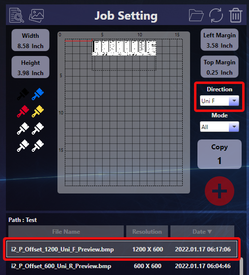
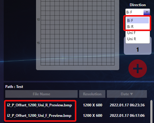
Set Direction to ‘Uni F’ and select the i2_P_Offset_1200_Uni_F_Preview.bmp test file in the Job Setting section of the i2 UI software. The image can be positioned as desired to use available space on a DTF sheet or other transparent plastic sheet.
Print the test image.
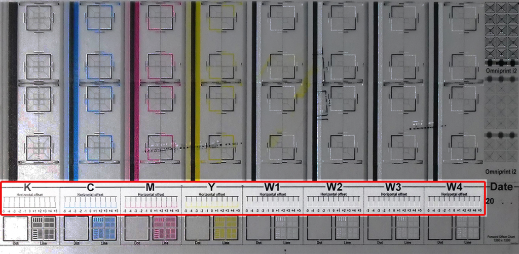
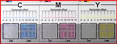
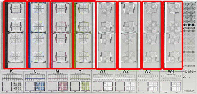
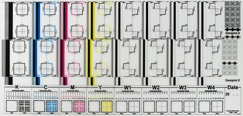
Analyze the test print to determine if adjustments are needed, focusing on the highlighted area in the image below.
First analyze the four white channels, W1, W2, W3, and W4.
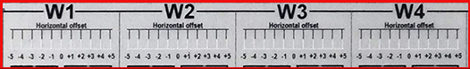
Each section (W1, W2, W3, and W4) has a series of numbers going from -5 to +5. Above each number are black & white vertical line segments. For each of these ‘W’ groups, identify which black & white pair form a single straight vertical line, or which is closest to a straight vertical line if none are perfectly aligned, and note the corresponding number of each.
In the pictured example, we would note the following: W1: +3 W2: 0 W3: +1 W4: +1
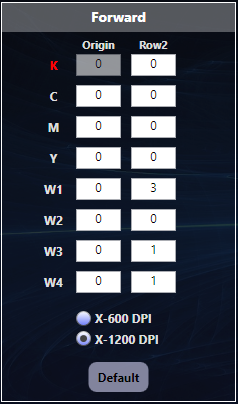
The next step is to sum (or add) the noted numbers to the values currently appearing in Row2 of the Forward Head Adjustment section. The image at the top of this section shows that the Row2 values in the Forward section for W1, W2, W3, and W4 are all ‘0’, so we have the easiest possible math of simply adding the noted numbers to 0.
After updating the values, click the Save button at the bottom of the Maintenance screen.
Loop through steps 3 through 7 until the black & white line segments for W1, W2, W3, and W4 each form straight vertical lines in the 0 (zero) position.
Once the whites are all aligned, find the number associated with the best-aligned vertical line pairs for Cyan, Magenta, and Yellow and sum them with numbers currently in the C, M, and Y rows of Row2.
The CMY channels in the above example already have the vertical lines perfectly aligned in the 0 (zero) position.
Reverse horizontal alignment
The process for the Reverse alignment is identical to the Forward alignment with the following exceptions.
Select the ‘X-1200 DPI’ setting at the bottom of the Reverse section on the Head Adjustment tab.
Select i2_P_Offset_1200_Uni_R_Preview.bmp in Job Setting.
Set Direction to ‘Uni R’.
When updating values based on analysis of the test print, sum with the current numbers in Row1 in the Reverse section of the Head Adjustment tab.
If values are updated we must click the Save button at the bottom of the Maintenance screen before continuing.
Bi-Directional horizontal alignment
Once the Forward and Reverse alignments are completed, we want to make sure the horizontal alignment is also good when printing in the Bi-directional mode.
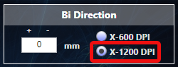
Start by clicking the X-1200 DPI option in the Bi Direction box.
Bi-directional alignment teseting can be done using either of the 1200 Uni offset test patterns: i2_P_Offset_1200_Uni_R_Preview.bmp or i2_P_Offset_1200_Uni_F_Preview.bmp.
Likewise, the Direction option in Job Setting can be set to either Bi F or Bi R.
After printing a test pattern, analyze the eight columns of stacked squares (one for each color channel), where each square is divided into four smaller squares.
In the above example, we can see that the bi-directional alignment is good because the upper pair of boxes in each column is aligned with the lower pair of boxes.
In the below example, the bi-directional alignment must be adjusted to make the upper and lower pairs of boxes line up with each other.
The position of the lower pair of boxes in each column is offset to the left of the upper pair of boxes (as well as the rest of the test pattern) by approximately 3mm. So to correct the alignment we will need to adjust the Bi Direction value by 3mm.
In this example, the Bi Direction value was set to zero (“0”) but you may find another number on your installation. To adjust the alignment we’ll want to change the value by either adding (+3) or subtracting (-3) to the current of zero.
Here’s how to know if you need to enter ‘3’ or ‘-3’ (the ‘+’ sign is not used).
If the above example was printed using the Bi F direction setting then we would enter ‘-3’, or if printed using the Bi R direction setting we would enter ‘3’.
Don’t worry too much about remembering which offset direction calls for entering a larger or smaller number. You can always change directions (upward or downward) if your entry made the offset worse. You can also use decimal fractions (2.7, for example) to fine-tune the alignment.
Remember to Save after each change before printing the next test patter.
White-Color Distance (Vertical Alignment)
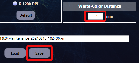
Vertical alignment of the two printheads is done using the White-Color Distance setting. As the software’s label describes, performing a vertical alignment is essentially calibrating the vertical position of the two printed ink layers as laid down by the separate white and color (CYMK) printheads.
Rather than using numbered line segments in a test pattern, as in the horizontal dimension, we simply evaluate any test pattern or design print. The adjustment is made by entering the number (in millimeters) by which the layers are out of alignment.
For example, let’s say the white layer is printing 3 mm above the color layer (as prints are oriented on the platen with the top of the design toward the front of the printer). To adjust the alignment we would enter “-3” in the White-Color Distance text box, then click the Save button.
After making an adjustment we always run another test print to see if we nailed it or if we need to make another adjustment.
You can have very high confidence that you will get excellent accuracy and detail when printing even the most challenging designs with all of the alignment options optimized!
The OmniPrint i2 printer uses the TCP/IP (Transmission Control Protocol/Internet Protocol) over an Ethernet connection to communicate with your PC, along with USB 3.0. The Ethernet connection requires a one-time configuration in Windows, which OmniPrint Training sets up for you during your initial training session.
The following information will help you to perform that same configuration if you should ever need to update your PC’s Ethernet adapter or if you’ve installed the i2 UI and Print Pro software onto a new PC.
Your OmniDTF printer and its software implementation are not designed to communicate over the Internet or any other network. We use a simple point-to-point connection between one PC and the printer, directly connected with a single Ethernet (“RJ45”) cable.
We configure TCP/IP parameters in the Control Panel of Microsoft Windows.
IP Address Configuration
Windows Control Panel’s Network and Sharing Center is where any Ethernet adapters to be used in a Windows PC can be configured. Use the steps demonstrated in the video below or the following step-by-step instructions to configure an Ethernet adapter for use with the i2. The video includes the Ethernet IP configuration process using the Windows 11 Settings app.
Video demonstration
Step-by-step instructions
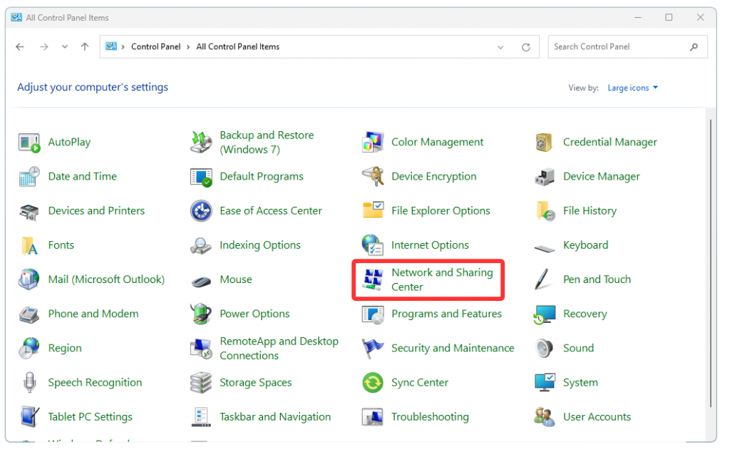
Run Windows Control Panel.
Click on Network and Sharing Center.
If you don’t see Network and Sharing Center in Windows Control Panel, it is because Control Panel is in the Category View mode. In that case, first click on Network and Internet, then click on Network and Sharing Center.
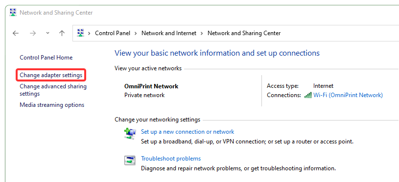
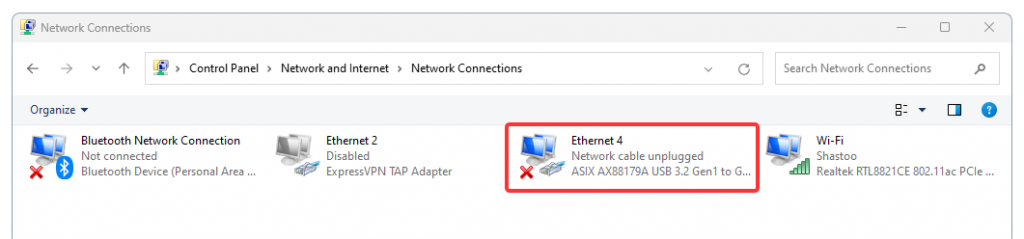
Select Change adapter settings
Double-click on the Ethernet adapter to be used (or right-click on the adapter and select Properties).
Your Ethernet adapter may have a different description than the Ethernet 4 pictured above. Don’t be concerned if there is a red ‘x’ on the adapter, which simply means that it isn’t currently connected to anything.
The ExpressVPN TAP Adapter does not represent a physical (actual) Ethernet hardware port and is not usable. This is strictly a “virtual” adapter built into Windows for creating VPN connections and has no purpose for the OmniDTF.
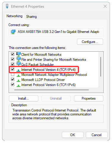
Double-click on Internet Protocol Version 4 (TCP/IPv4) (or single-click on it and then click the Properties button).
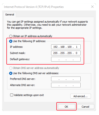
Click the Use the following IP address radio-button (if it isn’t already selected) and enter the following, then click ‘OK‘. IP address: 192.168.100.1 Subnet mask: 255.255.255.0
Stay on top of these few, easy maintenance tasks to keep your OmniPrint i2 reliably printing at maximum quality.
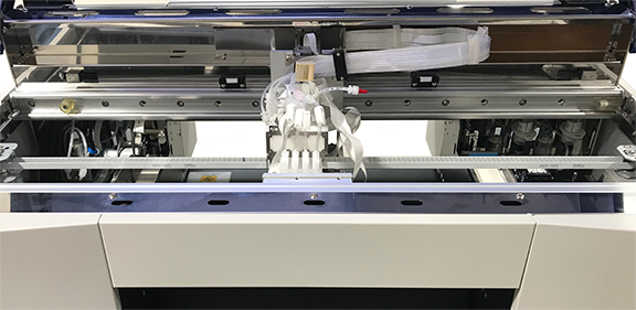
Clean the carriage encoder strip
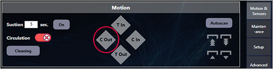
Release the printhead carriage from its Home position using the C Out (carriage out) button on the the Motion & Sensors tab of the i2 UI program.
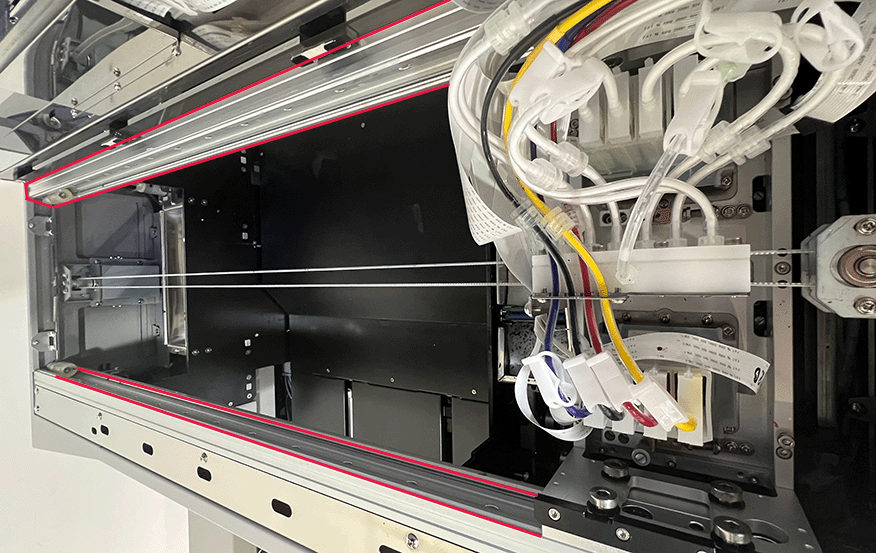
Clean the exposed section of the encoder strip with a lint-free cloth wetted with 70% isopropyl alcohol.
Manually reposition the carriage further to the left then clean the section of the encoder strip previously blocked by the carriage.
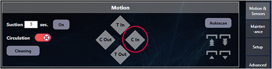
Return the carriage to its Home position using the C In (carriage in) button on the Motion & Sensors tab of the i2 UI program.
Clean & Lube the Carriage Rails
Release the printhead carriage from its Home position using the C Out (carriage out) button on the the Motion & Sensors tab of the i2 UI program.
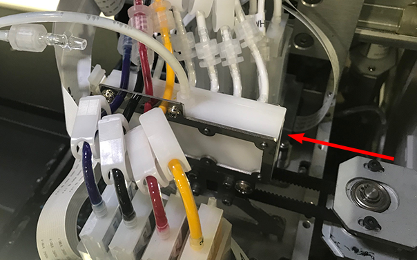
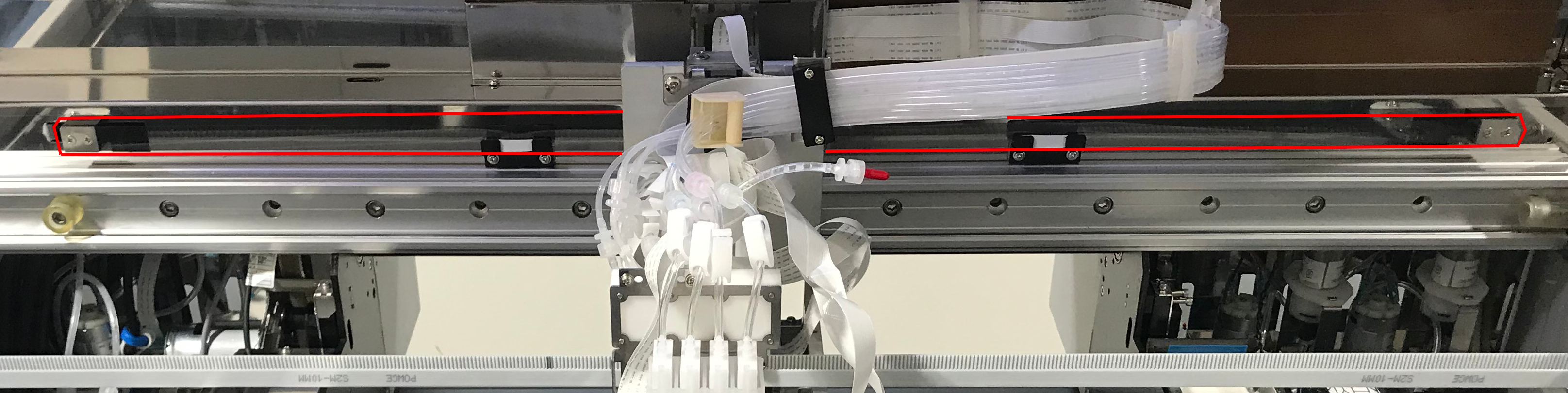
Wipe the exposed section of the front & rear carriage rails (outlined in red below) with a clean, dry, lint-free cloth.
Reposition the printhead carriage further to the left to expose the section of the carriage rails previously behind it and clean that section.
Apply dabs of blue grease to the top, bottom, and face of the front & rear rails, then move the carriage back and forth to distribute the grease across the full width of the rails.
Clean off any excess grease, then return the printhead carriage to its Home position using the C In (carriage in) button on the Motion & Sensors tab of the i2 UI program.
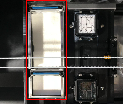
Clean the Spit Trays
Clean any excess ink from the spit trays and replace the soak pads, as needed.
Properly shutting down your OmniPrint i2 printer at the end of a production day is the most critical maintenance task.
This shutdown maintenance supports producing high-quality prints and maximizing economical operation. That’s because everything we do during the shutdown routine is focused on protecting and prolonging the service life of the printheads.
Process Summary
Run a head cleaning.
Close the ink clips.
Clean the wiper blades.
Clean the capping station seals.
Clean the printheads’ undercarriage.
Flush ink residue from the capping stations.
Wet cap the printheads.
Clean up any ink under the capping stations.
Exit the i2 UI program.
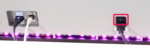
Turn of the i2 printer’s power.
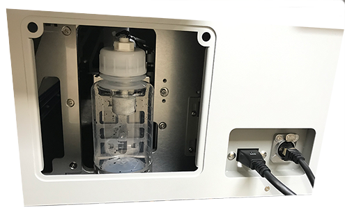
Empty the waste ink bottle.
Illustrated Step-by-Step Details
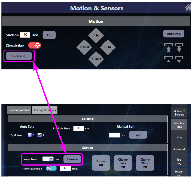
Run a head cleaning by clicking the Cleaning button on either the Motion & Sensors or Maintenance screen.
Close the ink clips
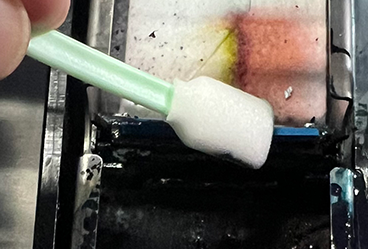
Clean the wiper blades with an anti-static foam swab or microfiber cloth wetted with Super Cleaner.
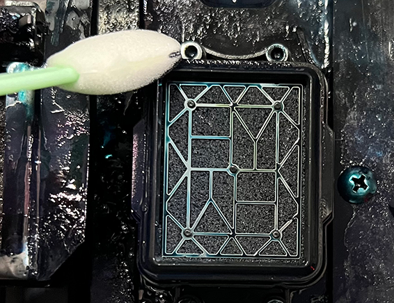
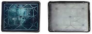
Clean the capping stations seals using an anti-static foam swab or microfiber cloth wetted with Super Cleaner.
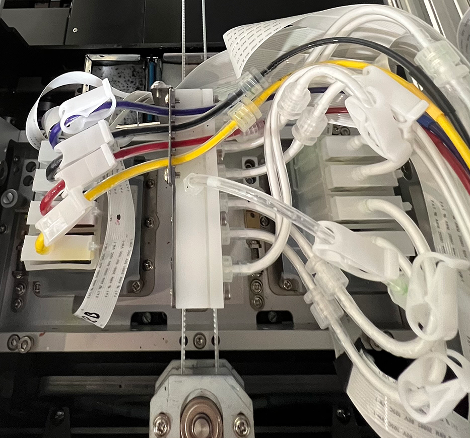
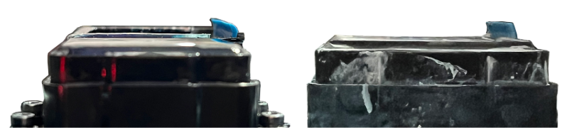
Clean any ink on the underside of the printheads mounting bracket and the side edges of the printheads, being careful to avoid contacting the mirror-like nozzle plates of the printheads (highlighted with a red tint below).
Flush ink residue from the capping stations.
Fill the capping stations with Super Cleaner.
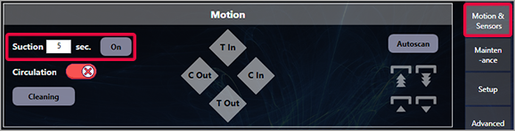
Run Suction to flush the Super Cleaner and any ink residue out the capping stations.
Repeat (or continually squirt Super Cleaner into the capping stations while Suction is running) until the loose ink is rinsed out.
Wet cap the printheads.
Fill both capping stations with Super Cleaner until you can see the surface tension of the liquid sitting slightly above the top of the rubber capping station seals.
Click the Home icon on the Motion & Sensors screen to send the carriage to its Home position, completing the wet cap process.
Clean up any liquid (ink or Super Cleaner) that may have spilled out of the capping station while flushing and wet capping.
Remove the right side access panel for access and visibility.
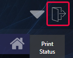
Exit the i2 UI program by clicking on the door icon in the upper-right corner of its window.