The Ink light on FreeJet printers will turn on from time to time. This normally has no effect on printing and it will turn off automatically within 15 minutes or less.
It turns on when part of the printer’s electronics which monitor ink usage have noted that nearly a cartridge worth of ink has been used for one or more of the 8 ink channels. You can ignore the Ink light since FreeJet printers use a bulk ink system rather than ink cartridges (reducing your costs and maintenance time).
So there is nothing that you need to do when your Freejet printer’s ‘Ink’ light comes on.
Your printer includes an ink chip reset feature which automatically notifies the ink monitoring system that a new ink cartridge has been installed, causing the Ink light to turn off. Note that the ink light will flash just before the reset is completed, but nothing needs to be done by the operator as this is an automated function.
If the Ink light is on when the printer is shut down, an ink chip reset will run and the Ink light will be turned off next time the printer is turned back on.
If you like, you may perform a manual ink chip reset to clear the light using the following steps:
Press Function + Stand by simultaneously.
Pause for 4-5 seconds.
Press Function + Stand by a second time.
If nothing seems to be happening when you press the button combination, try pressing the Function button a half-second before pressing the Stand by button, then release them both.
The below video explains the purpose and mechanics of pretreatment, including valuable pro tips about garment quality, pretreatment troubleshooting, and pretreat equipment placement and maintenance.
In the below video and the following step-by-step instructions, we demonstrate how to rip an image or Layout to get the ink cost without printing. We’ll also show you how to save the ripped Layout to a file, including all sizing and configuration settings, and also how to load a previously saved rip for immediate printing.
Rip Without Printing
Once you have images and Layouts fully configured and ready to print, it’s simple to rip them without printing. Features of Print Pro’s Queue Manager can then be used to do things like determine the cost of ink needed to print the rip or to save the fully configured rip and quickly load and print it in the future.
For a refresher on how to set up images and Layouts see the Setting Up a Print knowledge base article.
Here’s how to rip an image or Layout in Print Pro.
First complete your image(s) and Layout setup, including sizing and creating the white underbase choke for the images.
Place the image(s) onto a Layout if you want to rip the full Layout.
Select the image or Layout you want to rip by clicking on it.
Click on the Add Job icon in the Queue Manager toolbar — the 2nd icon from the left.
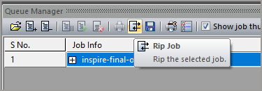
Right-click on the new item added under the Queue Manager’s Job Info heading, then click on Rip. You may instead select the new line, then click the Rip Job icon on the Queue Manager toolbar — the 8th icon from the left.
Queue Manager’s Status column will display “Ripping…” as it begins ripping the job. This message will change to “RipDone” when the rip is finished.
Viewing Ink Costs of a Ripped Job
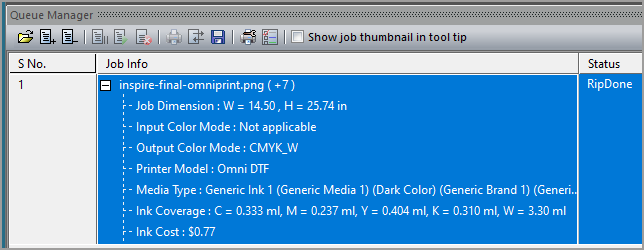
Click on the ‘+’ symbol to the left of the ripped job’s name in Queue Manager’s Job Info column.
Scroll down the expanded view in the Job Info column to find the amount and cost of each ink color used in the design, as well as the total ink cost.
Saving a Ripped Job
Saving a ripped job is a two-step process. We first tell the software where we want the file to be saved, then we save it.
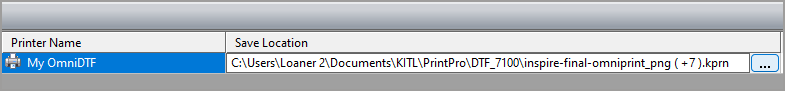
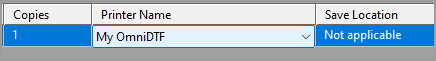
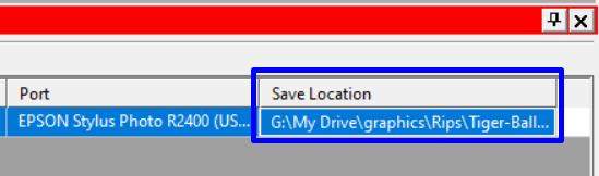
Review the Save Location for the ripped file in the far right column of Queue Manager. If you want to save the rip to the currently designated location, skip to step 5.
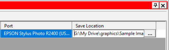
Under the Save Location heading, click on the line of the ripped job that you want to save.
Click on the ellipses (“…”) that appear at the right end of the line that you clicked on.
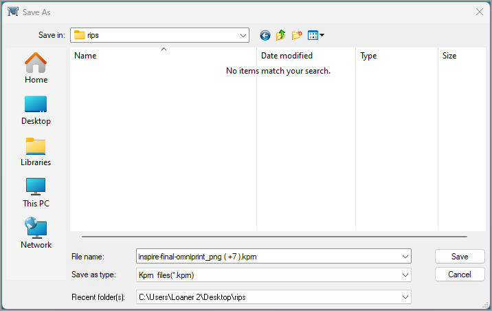
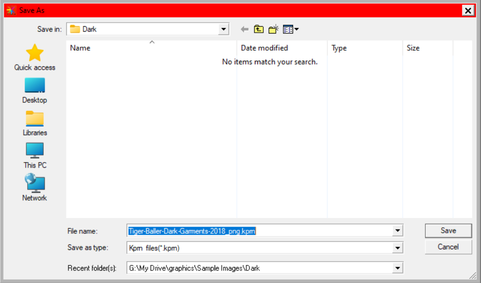
In the “Save As” window that appears, navigate to the folder where you want the rip to be saved, and click on the Save button. This does not save the rip. It simply lets you edit the filename to be used and saves the location where the rip will be saved when you do save the rip in the next step.
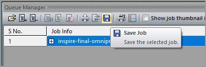
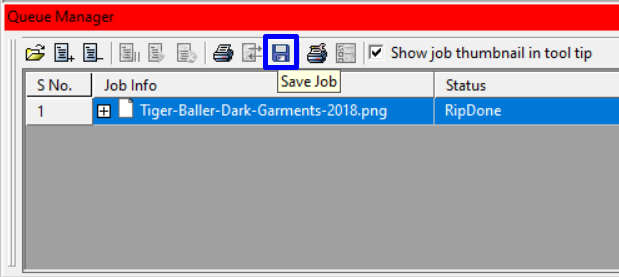
Click on the Queue Manager’s Save Job button (a disc icon) to save the rip to your designated location.
Loading a Saved Rip
Loading a saved rip is quick and easy. Since all image and Layout parameters were included when the ripped file was saved, once the rip is loaded it can be immediately printed.
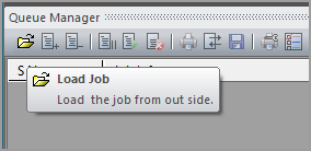
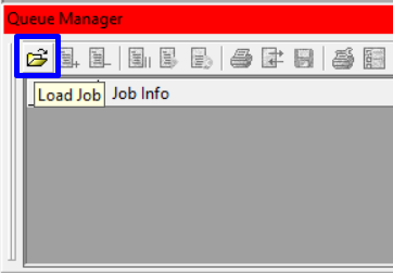
Click on Queue Manager’s Load Job icon. The first icon from the left, with the appearance of an open folder.
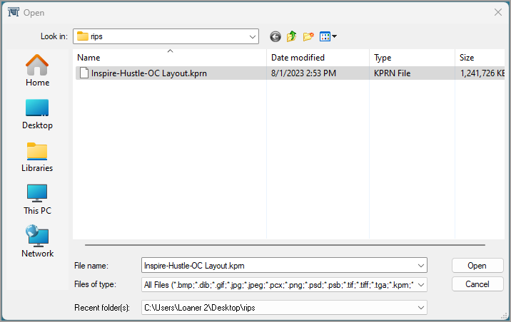
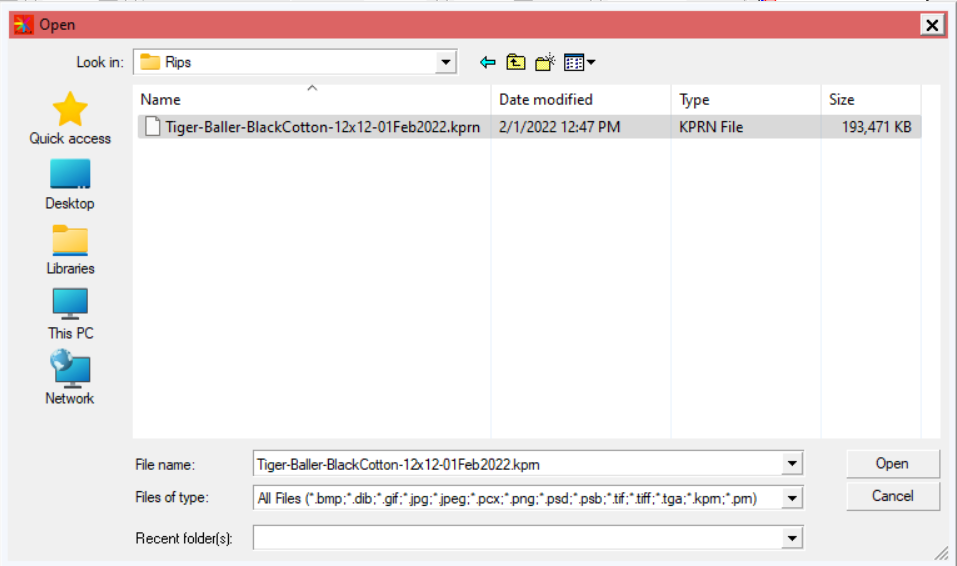
In the File Open window that appears, navigate to the folder where the rip file you want to print was stored, then select the rip file and click Open.
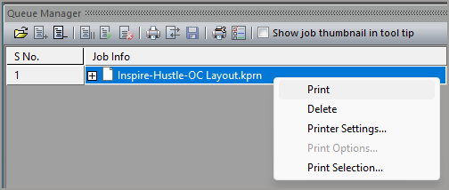
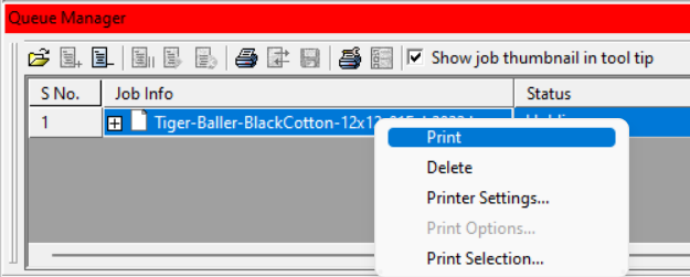
When the saved rip appears in Queue Manager’s Job Info column, right-click on it and select Print or click on the Print Job icon in Queue Manager’s toolbar.
If the print options are grayed out, ensure your printer is selected in Queue Manager’s Printer Name column.
Print Pro DTF Environments are collections of preset options used to select the printing resolution and other parameters when setting up a print job for the OmniDTF or Omni DTF Mini.
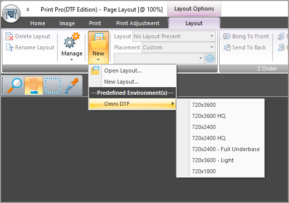
Installed Environments are found in Print Pro DTF by selecting the Layout tab, then clicking on New and hovering over Omni DTF or Omni DTF Mini.
To update the Environments in Print Pro for your DTF printer, download the file for your model at the bottom of this article and follow the instructions in the below video or the following written steps. The process is identical for the OmniDTF and the Omni DTF Mini.
Video Demonstration
Installing the Environments
The installation process of the Environments is quick and easy.
Download the Environments file to the PC on which you’ve installed Print Pro.
See the download links at the bottom of this article.
Unzip the contents of the downloaded .zip file (a single .kiee file).
Placing the downloaded file on the Windows Desktop is recommended to easily find the file. It can be deleted after this installation process.
Run Print Pro.
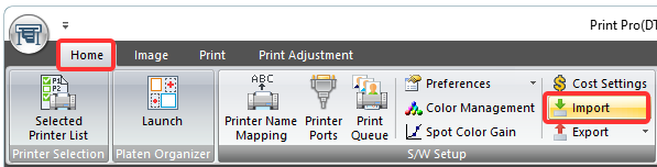
Select the Home tab, then click the Import button.
Select the .kiee file that was downloaded, then click the Open button.
If prompted with a message of “Already ‘Omni DTF-720×3600’ environment exist.” (The actual environment name will vary), click the Yes button.
If prompted to Select environment settings to use, select ‘Use new environment settings only’ and click OK.
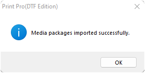
Click OK on the “Media packages imported successfully” window.
Exit out of the Print Pro program, then restart it.
The OmniDTF or Omni DTF Mini Environments have now been updated and are ready for use.
Please note that the number of Environments available for the Freejet 330TX and 330TX Plus has been expanded significantly since this manual was published.
See the DTF Environment Guidelines & Troubleshooting Tips document linked in the Attachments section below for details on the use of those Environments.
The updated Environments are available from the Installing Freejet DTF Environments in the Related Articles section below.
Download the DTF for Freejet Manual from the below link.
DTF printing comes with its own unique set of advantages so many DTG printer operations are running some of their print jobs using the DTF technique!
Freejet printers are fully capable of printing vibrant, durable, and profitable transfers. Best of all, expanding your Freejet operation to include film transfer printing is easy, requiring just a few modifications to your software and workflow!
This guide will take you through the process of importing the latest DTF Environments for the Freejet 330TX or 330TX Plus into DirectRIP, so you can try out this exciting kind of garment printing yourself!
Loading the DTF environments into DirectRIP
Download links for the Freejet 330TX and 330TX Plus DTF Environments (.kie files) are listed at the bottom of this article.
Make sure that the file that you download matches your printer model as the different inks in the 330TX and the 330TX Plus require different Environments. Using the incorrect environment can result in ink bleeding or poor adhesion.
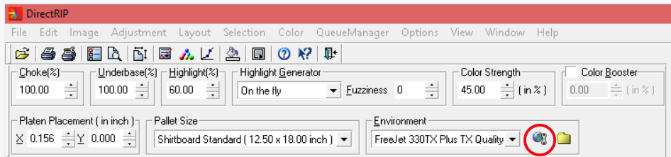
In DirectRIP, next to your “Environment” drop-down box, there is an icon that looks like a globe with a wrench for ‘Manage Environment’.
Click this ‘Manage Environment’ icon.
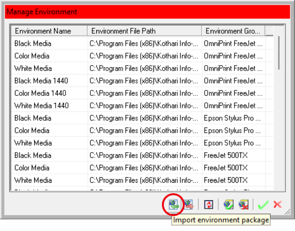
The ‘Manage Environment’ window will open. Click the leftmost icon at the bottom of this window to open the ‘Import Environment Package’ window.
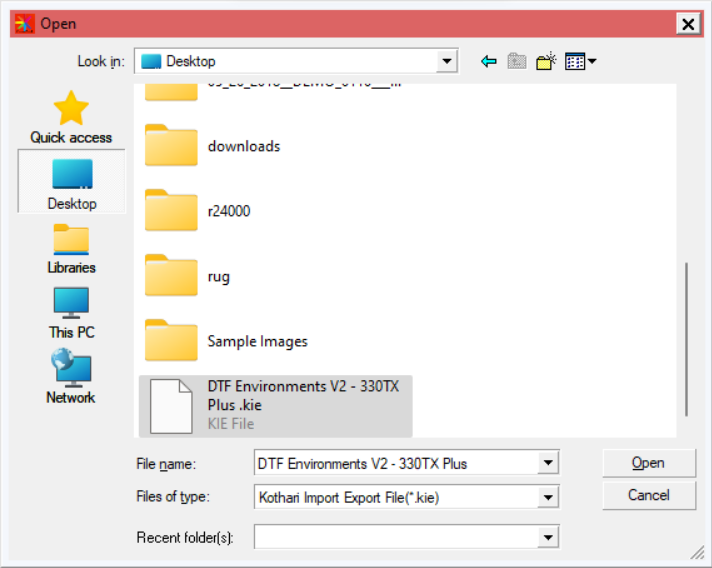
In the window that appears, navigate to where you saved the downloaded .kie file, select it, and click the ‘Open’ button.
The below screenshot examples are for a previous version of Environments for the Freejet 330TX Plus. There will be differences in file & Environment names for later versions, but the process is the same.
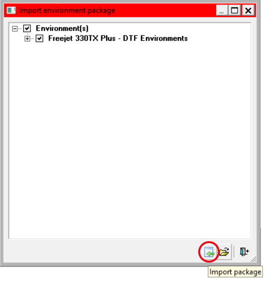
You should arrive at this window:
Click the ‘Import Package’ icon. This will import the new environments and the ‘Import environment package’ window will automatically close.
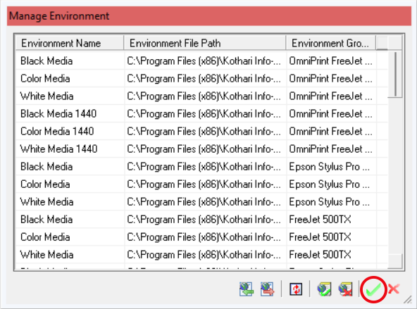
Next, click the green checkmark on the ‘Manage Environment’ window to save the update and close the menu.
That’s it! The environments are now fully installed! You can now use them to print transfers!
It’s important to have a basic understanding of how the ink delivery system works and the parts that are involved. Knowledge is power, and understanding the basics of how ink gets from the bottles to the print head empowers us to use deductive reasoning to quickly troubleshoot and resolve most ink flow issues.
Here’s a full list of the components of the ink delivery system:
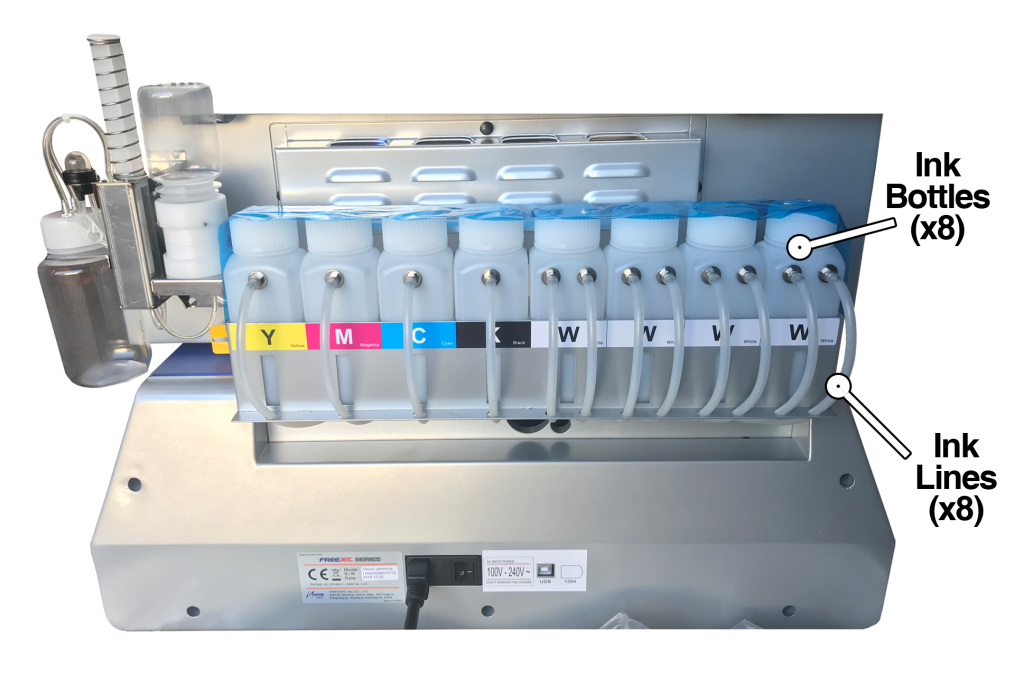
Ink bottles (8)
Ink lines (8)
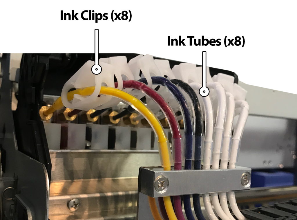
Ink tubes (8)
Ink clips (8)
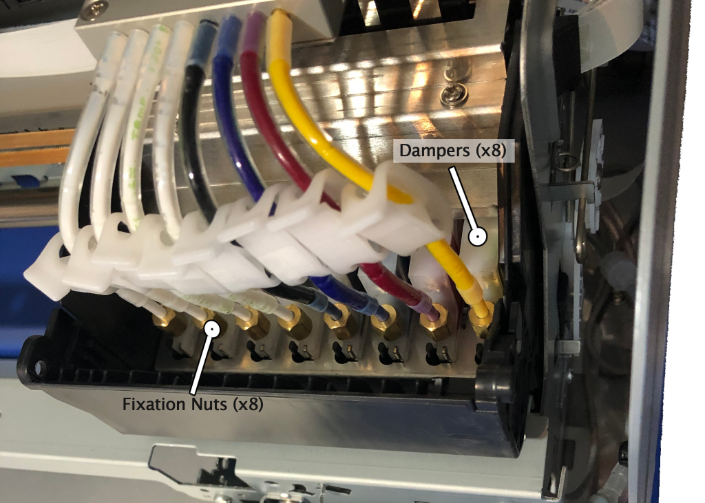
Dampers (8)
Damper fixation nut (8)
O-rings (8)
Print head
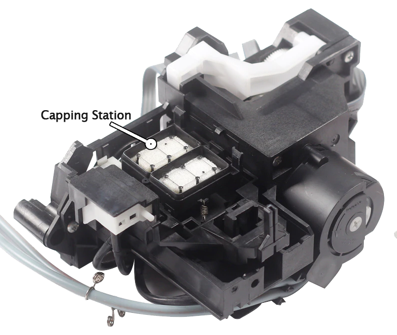
Pump with capping station
Since we have eight ink channels (cyan, magenta, yellow, black, and four whites), there are eight of each part in the ink path until we get to the print head.
Let’s first define the purpose of each component, and then we’ll briefly go over how they all work together to get ink from the bottles and onto the garments when we print.
Component Functions
Ink bottles: The ink bottles provide a reservoir of ink for each channel. These are the beginning of the ink path for each of the eight ink channels. Each bottle has a metal fitting, through which an ink line will pass as it moves out of the bottle.
On the Freejet 330TX Plus model, there will be a second fitting on each white ink bottle. This is where white ink returns to the bottle when the circulation pumps are running. However, this white ink circulation circuit isn’t functionally part of the ink delivery system so won’t be detailed further here.
Ink lines: The translucent, plastic ink lines provide the majority (roughly 90%) of the path between the ink bottles and the print head. In combination, they’re an 8-lane ink expressway with no stops and no lane changes allowed.
One end of each ink line passes through a fitting on its ink bottle and extends down to about 1/4″ to 1/2″ from the bottom of the bottle. The other end of each ink line terminates inside the gantry, where it connects to an ink tube.
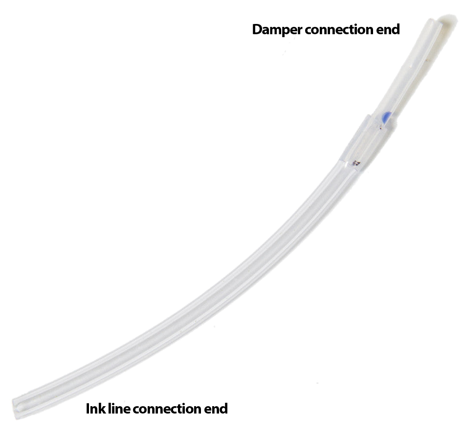
Ink tubes: The short (about 3″), softer plastic ink tubes are the “last mile” of the ink path, providing a flexible interconnection between the ink bottles and the dampers. If the ink lines are an ink expressway then the ink tubes are the off-ramp where the ink has almost reached its destination.
The Ink Tube connects the ink line to the damper.
The larger end of the ink tube tightly slips around the ink line, while the small end is attached to the damper with an o-ring and copper-colored nut.
Ink clips: The purpose of the ink clips is to crimp the ink tubes and shut off ink flow when desired (such as when the printer is idle.)
Dampers: Dampers provide the final “Quality Assurance” for ink with their mesh filter, which serves to trap bubbles and any dried ink or foreign material that doesn’t belong in the ink supply. (Better to replace a clogged damper than to have to replace a clogged print head.)
Damper fixation nuts & O-rings: These two parts complete the air-tight, mechanical connection between the ink tube and the damper. The o-ring goes around the smaller end of the ink tube and presses against the inside of the fixation nut to ensure an air-tight connection when the nut is attached to the damper.
The dampers and their associated o-rings and fixation nuts are the last components in the printing ink path before the print head.
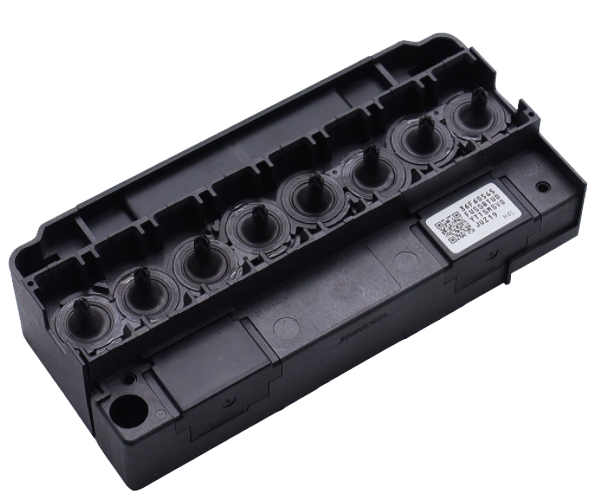
Print head: The print head is where it all comes together — literally. All eight of the ink channels feed into the eight posts on top of the print head, to which the dampers directly connect.
Print head top, with damper posts.
The purpose of the print head is, of course, to deliver the ink to the garment that we’re printing onto through the over 1,400 tiny nozzles of the print head plate, on the bottom of the print head.
All of the components listed above except the print head itself are completely passive while the printing. That is, they are simply a conduit for the ink to travel through.
Pump with capping station: Ink doesn’t actually flow through the pump when we’re printing, but it’s included here because it is instrumental for priming and for running head cleans before or between print jobs.
The purpose of the pump, with regards to ink delivery, is to pull ink through the print head nozzles when priming and running head cleans, but not when printing.
Ink Flow Dynamics
When printing, ink is jetted out of the print head nozzles by micro-piezo electronics within the print head. This creates pulses that push drops of ink out of nozzles as the carriage moves back & forth. This happens very quickly and very precisely in order to produce high-quality prints at high resolution.
You may wonder, if it’s only the print head that actively does anything to make ink flow while printing, what causes the ink to flow into the print head while printing? Essentially, it is gravity — but more specifically, the ink delivery system is a type of siphon. As the print head expels drops of ink, the siphon effect causes more ink to be drawn into the print head from the bottles, through the ink lines, tubes, and dampers.
In order for ink to flow properly through a siphon system, every component and connection in the system must be air-tight. So while this isn’t a troubleshooting guide, if one of your ink channels starts dropping out while printing after getting a perfect nozzle check, you may want to verify the following:
While configuring an image for a print job becomes practically muscle memory for operators after a modest amount of practice, it can, nonetheless, become a bottleneck in your production process. You may wish to save the configuration settings of some print jobs for efficient recall at a later time. We’re happy to tell you this is absolutely possible, with just a few details to keep in mind.
The process is essentially the same for Freejet printers using DirectRip and for the OmniDTF using Print Pro DTF. The program’s internal windows are styled a bit differently but the toolbar icon locations & functions in the Queue Manager of both rip software versions are identical. The still images shown are from DirectRip while the videos are from Print Pro DTF.
Before saving print job configurations, you may want to create a folder on your PC for your saved configurations. Sub-folders divided up by image, client, and/or job type would be a wise choice as well. You’ll see why in just a moment.
The next step is to configure your print job in DirectRip or Print Pro as usual. When the print is completely configured and ready, it’s time to Rip the image. You can do that by simply printing the design, which always involves first creating a Rip. Or if you just want to save these settings to print later, you can create a Rip without printing.
Ripping a Print Job without Printing
To create a Rip without printing, with your print job fully configured, we will be using features of the ‘Queue Manager’ subwindow at the bottom of the rip software as demonstrated in the below video and the following instructions.
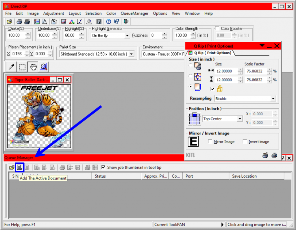
In Queue Manager, click the “Add the Active Document” icon, which looks like a sheet of paper with a ‘+’ sign in its lower-right corner.
The image’s filename will then appear in Queue Manager’s Job Status column. Right-click the filename, then select ‘Rip’ from the options that appear in the pop-up menu .
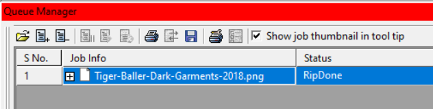
When the Rip has been completed, the Status column in Queue Manager will read “RipDone”.
Saving the Ripped Print Job
Whether you ran a print or used Queue Manager to Rip without printing, once the job has been Ripped, it will be ready to save using the process demonstrated in the below video or the following instructions.
On the far right of the Queue Manager frame, find the column labeled “Save Location”.
Click anywhere in the cell or box displaying the file system path of the current Save location.
The ellipses (“…”) at the end of the path will then turn into a button.
Click the ellipses button that appears to edit the location and filename to be used when saving your Rip file. This will open your file browser. At this point, navigate to the folder in which you want to store the Rip.
After picking the folder, it is recommended that you give the job a new file name. Keep in mind that when selecting a saved print job to load in the future, you will not have a thumbnail or preview of the image. So, not only will the image in the file need to be identifiable from its name, but also the Environment, sizing, placement, and any other variables you may have adjusted when setting up the print job which makes it distinct from other, similar prints. (The file extension of all saved Rips will be .kprn.)
I recommend using something like: “<Image>_<Environment>_<Size>_<Date>”. For example: “TestImage_Dark_10x6_28Jan2022.kprn”. This will be instrumental to finding the file that you want to load for future printing sessions, to ensure that you have the correct version of any Rip file for the shirt you intend to print.
Once you’ve selected the Save Location and entered the filename to use, click the ‘Save’ button. Note that this action only saves the desired file name and location. You haven’t yet saved the actual Rip of the print job.
Next, click the ‘Save job’ disk icon in the Queue Manager toolbar to save the settings to a file.
Once you have clicked the ‘Save Job’ icon, the Rip is saved to the designated folder and filename, and it is safe to close DirectRip.
Recalling a Saved Print Job
To recall the file for later use, open DirectRip but don’t load an image file. Next, instead of loading an image file, we will load a previously saved print job using the Queue Manager.
The leftmost icon at the top of the Queue Manager subwindow, the open folder icon, is the “Load Job” option. Click this icon to open a file browser.
Next, navigate to the folder where your custom job is saved, select the appropriate file, and click “Open”.
The job will populate in the Queue Manager, ready to go!
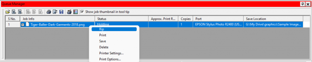
DirectRip’s top-level menus and the Print buttons in the top toolbar and Q-Rip subwindow will all be greyed out since we haven’t loaded an image file. That’s fine because you will use the Print button in Queue Manager’s toolbar to run your print. As an alterative to the Print button, you can also right-click the filename in the Job Info column and select ‘Print’ from the pop-up menu.
This pop-up menu appears after right-clicking the filename in the Job Info column
Notice, as mentioned above, the image to be printed isn’t displayed in DirectRip. However, you’ve already confirmed the configuration of this print job before saving it, so as long as you have the printer started up and in the Print Ready position with a shirt pretreated and loaded on the platen, you are ready to print.
Click the Print icon or right-click the filename in the Job Info column and select ‘Print’ to run the print job.
Enjoy the increase in efficiency for designs that you will be using for multiple print jobs!